Poor electrical panel design creates cascade failures in industrial systems, causing expensive downtime, safety hazards, and maintenance nightmares. I've witnessed these preventable disasters repeatedly when working with clients who overlooked mounting system fundamentals.
An MCCB pan assembly is a specialized mounting plate designed to securely install molded case circuit breakers in electrical distribution panels. It provides structural support, proper electrical clearances, simplified connections to busbars, and standardized installation, enabling safe operation and easier maintenance of circuit protection equipment.

In my decade of working with electrical distribution systems, I've discovered that while engineers obsess over circuit breaker specs, they often underestimate how mounting systems affect long-term reliability. This oversight leads to costly issues that could have been easily prevented with the right pan assembly choice.
What Does MCCB Mean on Breaker?
Engineers and facility managers often struggle with electrical terminology and worry about specifying the wrong equipment, potentially creating safety hazards or compatibility issues that derail projects.
MCCB stands for Molded Case Circuit Breaker, a type of electrical protection device encased in a molded insulating material housing that safeguards electrical systems from overloads and short circuits. Unlike standard breakers, MCCBs handle higher currents (typically 100-1200A), offer adjustable trip settings, and provide superior interruption capacity.

I remember visiting a manufacturing facility where production kept halting due to mysterious electrical failures. After investigation, we discovered they had installed standard breakers instead of MCCBs in an application with frequent motor startups. The resulting voltage dips and nuisance tripping cost them thousands in lost productivity daily. Proper MCCB installation solved their problem completely.
MCCBs differ significantly from standard miniature circuit breakers (MCBs) in several important ways that affect how they need to be mounted and connected:
Key Characteristics of MCCBs
| Feature | Description | Impact on Pan Assembly Requirements |
|---|---|---|
| Current Rating1 | Typically 100-1200A | Requires robust electrical connections and heat dissipation |
| Physical Size | Larger, heavier construction | Needs stronger structural support |
| Adjustable Trip Settings | Configurable overload and short-circuit protection | Must allow access to adjustment dials/controls |
| Interrupting Capacity2 | Higher fault current handling (10-100kA) | Demands secure mounting to withstand electromagnetic forces |
| Terminal Design | Often accepts multiple conductor sizes | Requires versatile connection options |
| Auxiliary Functions3 | May include shunt trips, alarms, etc. | Assembly must accommodate additional wiring |
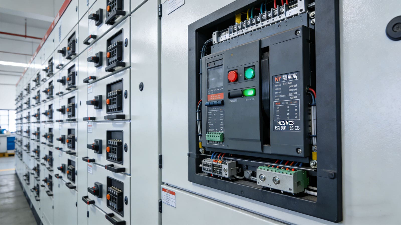
MCCBs serve as critical protection components in industrial, commercial, and infrastructure applications where reliability is paramount and fault currents can be extremely high. Their robust construction and advanced protection capabilities make them ideal for main distribution panels, motor control centers, and critical power systems.
What is Pan Assembly?
Electrical contractors and panel builders frequently face delays and safety issues when mounting systems don't align properly, causing frustration and budget overruns that could be avoided with standardized solutions.
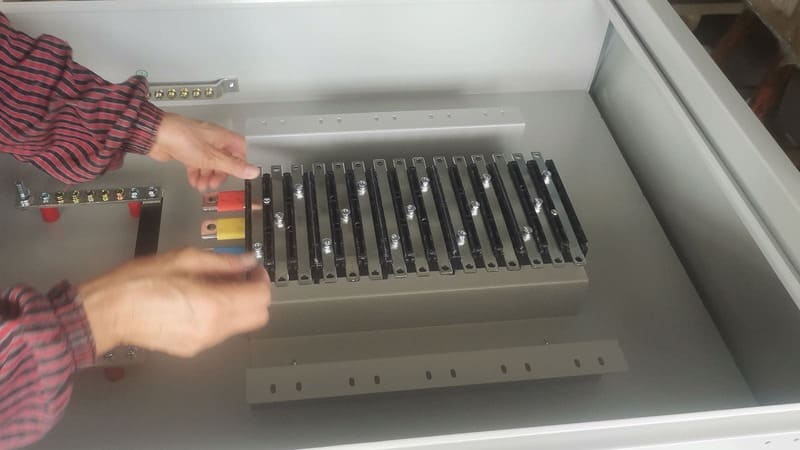
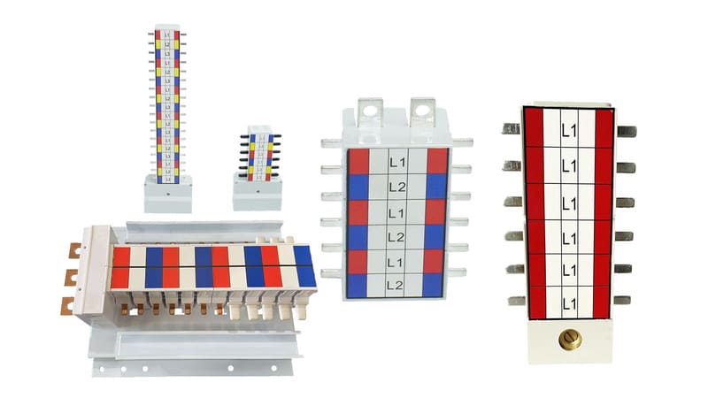
A pan assembly is a pre-engineered mounting platform that simplifies the installation of circuit breakers by providing a standardized base with proper spacing, connection points, and mechanical support. It integrates breaker mounting, electrical connections, and often includes busbars, creating a modular system that ensures correct installation and maintains required clearances.

During a recent power upgrade project for a data center client, using our pre-engineered pan assemblies reduced installation time by nearly 40% compared to their previous custom-built approach. Their facility manager later told me this was critical to meeting their aggressive timeline for bringing new servers online.
The value of properly designed pan assemblies extends far beyond mere convenience - they fundamentally improve electrical system reliability and safety through several key functions:
Functions and Benefits of Pan Assemblies
| Function | Benefit | Real-World Impact |
|---|---|---|
| Structural Support4 | Prevents mechanical stress on connections | Reduces failure risk during vibration or thermal cycling |
| Standardized Mounting | Ensures proper alignment and clearances | Eliminates installation errors and improves maintenance access |
| Busbar Integration | Creates reliable power distribution paths | Reduces connection points and potential failure points |
| Heat Management5 | Proper spacing allows thermal dissipation | Prevents premature component aging and maintains rated performance |
| Future Flexibility6 | Modular design enables reconfiguration | Simplifies upgrades and modifications without complete rebuilds |
| Safety Compliance | Maintains required isolation distances | Ensures compliance with electrical codes and standards |
I've found that quality pan assemblies typically incorporate features that anticipate real-world installation challenges. These include pre-drilled mounting holes with proper spacing, integrated phase barriers, clearly marked connection points, and robust construction that maintains integrity even when panels are transported or subjected to vibration.
For facilities with critical power needs or those planning future expansion, investing in high-quality pan assemblies provides both immediate installation benefits and valuable future flexibility that often pays dividends throughout the system's lifecycle.
What is the Reason for MCCB Tripping?
Facility managers and maintenance teams face stressful emergency situations when unexpected circuit breaker trips shut down critical operations, creating pressure to quickly identify complex root causes.
MCCBs trip primarily due to overloads (excessive current over time), short circuits (sudden massive current flow), ground faults (unintended path to ground), or internal failure of the breaker mechanism itself. Improper mounting on inadequate pan assemblies can contribute to these issues through loose connections, overheating, or mechanical stress.

I recently worked with a manufacturing plant experiencing mysterious MCCB trips that were shutting down production lines. After thorough investigation, we discovered their pan assemblies had insufficient copper cross-section for the heat generated at full load. The resulting thermal stress was causing nuisance tripping. Upgrading to properly rated pan assemblies completely resolved the issue.
Understanding the relationship between pan assembly quality and MCCB tripping is essential for reliable electrical system design:
MCCB Tripping Causes and Pan Assembly Factors
| Trip Cause | Technical Explanation | Pan Assembly Contribution | Prevention Approach |
|---|---|---|---|
| Overload | Current exceeds rated value for extended period | Inadequate conductor sizing or poor connections increase resistance and heat | Properly sized busbars and secure connection points |
| Short Circuit | Direct connection between phases or phase-to-ground | Insufficient phase separation or insulation degradation from mechanical stress | Robust phase barriers and proper clearances |
| Ground Fault | Current finding alternative path to ground | Improper insulation or moisture ingress due to poor mounting | Quality insulation materials and proper environmental protection |
| Thermal Stress | Heat buildup exceeding MCCB tolerances | Inadequate ventilation space or heat dissipation paths | Designed airflow channels and proper spacing |
| Mechanical Failure | Physical damage to internal MCCB components | Vibration transfer or mounting stress on MCCB housing | Vibration isolation and proper structural support |
Through years of troubleshooting electrical distribution problems, I've found that many "mysterious" MCCB tripping7 issues ultimately trace back to mounting system deficiencies. When pan assemblies8 are properly engineered for the specific application conditions, nuisance tripping incidents decrease dramatically, and system reliability improves measurably.
For critical applications, I often recommend pan assemblies with temperature monitoring capabilities or designs that facilitate thermal imaging inspection9. These features allow maintenance teams to identify potential issues before they escalate to disruptive trips.
How to Read MCCB Rating?
Electrical system designers and maintenance personnel often struggle to interpret the complex rating information on MCCBs, risking inappropriate application that can lead to protection gaps or unnecessary expenses.
MCCB ratings include frame size (maximum possible ampacity), actual current rating (normal operating capacity), voltage rating (maximum system voltage), interrupting capacity (maximum fault current handling), and trip class (response characteristics). These ratings must match both the electrical system requirements and the pan assembly specifications.

When helping a client specify replacement breakers for an aging industrial system, I found they'd been consistently over-specifying interrupting capacity out of caution. By conducting a proper fault current study and matching MCCBs to actual requirements, we saved them over 30% on replacement costs while maintaining appropriate safety margins.
Correctly matching MCCB ratings with pan assembly specifications involves understanding several critical parameters:
Key MCCB Rating Parameters
| Rating Parameter | What It Means | Pan Assembly Consideration | Practical Example |
|---|---|---|---|
| Frame Size | Physical size class that determines maximum possible ampacity | Must match mounting hole pattern and physical dimensions | 250A frame requires specific mounting pattern regardless of actual current setting |
| Current Rating10 | Maximum continuous current the breaker is adjusted to carry | Busbar capacity must equal or exceed this value | 160A MCCB needs minimum 160A busbar capacity |
| Voltage Rating | Maximum system voltage the MCCB can safely interrupt | Insulation and clearance requirements | 690V rated MCCB requires greater phase-to-phase spacing |
| Interrupting Capacity | Maximum fault current the breaker can safely interrupt (kA) | Structural strength to withstand magnetic forces during faults | 65kA MCCB needs more robust mounting than 25kA version |
| Trip Class11 | Response curve characteristics (standard, motor protection, etc.) | Access to adjustment dials if applicable | Electronic trip units may need front panel access space |
| Connection Type | Terminal design (front/rear connections, lugs, etc.) | Must accommodate specific connection method | Back-connected MCCBs require specific bus arrangements |
Reading MCCB ratings effectively requires understanding both the explicit rated values and their implications for the mounting system. For instance, higher interrupting capacities create stronger magnetic forces during fault conditions, requiring more robust pan assemblies to maintain integrity.
I've found that creating a systematic matching process between MCCB specifications and pan assembly capabilities prevents costly errors and ensures long-term reliability. This process should include verification of physical dimensions, electrical capacities, connection methods, and environmental factors like operating temperature ranges.
Conclusion
Choosing the right MCCB pan assembly is far more than a mechanical decision—it directly impacts your electrical system's safety, reliability, and future adaptability. By understanding how these mounting systems affect breaker performance and planning for both current needs and future modifications, you'll avoid costly downtime and create more resilient power distribution systems.
-
Understanding current rating is crucial for ensuring proper electrical connections and heat management in MCCBs. ↩
-
Exploring interrupting capacity helps in grasping how MCCBs handle fault currents effectively, ensuring safety and reliability. ↩
-
Learning about auxiliary functions can enhance your understanding of additional features that improve MCCB functionality and safety. ↩
-
Understanding structural support can help you appreciate how pan assemblies enhance reliability and reduce failure risks. ↩
-
Exploring heat management in pan assemblies reveals how they prevent component aging and maintain performance, crucial for longevity. ↩
-
Learning about future flexibility can guide you in making informed decisions for upgrades and modifications in your systems. ↩
-
Understanding MCCB tripping causes can help prevent electrical failures and improve system reliability. Explore this resource for detailed insights. ↩
-
Learn how well-designed pan assemblies can enhance system performance and reduce nuisance tripping incidents. This resource provides valuable information. ↩
-
Discover how thermal imaging can proactively identify issues in electrical systems, preventing costly downtimes. This link offers essential knowledge. ↩
-
The Current Rating directly impacts the performance and safety of MCCBs. Discover more about its significance in this resource. ↩
-
Different Trip Classes cater to various applications, affecting protection strategies. Learn more about their applications and benefits here. ↩