Choosing between busbar pan assemblies and direct feed connections confuses many electrical engineers. The wrong choice can lead to wasted panel space, difficult maintenance, or even compromised system reliability. Which option is right for your specific application?
A busbar pan assembly is a prefabricated mounting system that distributes power to multiple circuit breakers through a common bus, while a direct feed system connects individual loads directly to the power source with dedicated conductors. Each serves distinct purposes in electrical distribution systems based on load requirements, space constraints, and future expansion needs.

I've guided countless customers through this decision process at our factory. Let me share what I've learned about these two fundamental power distribution approaches to help you make the right choice for your electrical systems.
What is a busbar assembly?
Have you struggled to understand exactly what a busbar assembly is and how it differs from traditional wiring methods? The terminology can be confusing, especially with various manufacturers using different terms for similar products.
A busbar assembly is an engineered power distribution system that uses solid metal bars (typically copper or aluminum) to efficiently distribute electrical power to multiple connection points, replacing individual wires and providing a more organized, reliable, and space-efficient power distribution solution.

When customers visit our production facility, I show them how busbar assemblies transform electrical distribution from the traditional "point-to-point" wiring approach to a more systematic and efficient method.
Busbar assemblies come in various configurations, but they all share the fundamental concept of replacing multiple individual conductors with solid metal bars that serve as common connection points. This creates several advantages in electrical systems:
Busbar Assembly Components and Functions
| Component | Function | Benefit |
|---|---|---|
| Main Busbar | Primary power distribution conductor | Higher current capacity in compact space |
| Insulation System | Maintains electrical separation between phases | Enhances safety and prevents short circuits |
| Mounting Hardware | Secures busbar to enclosure | Ensures physical stability during operation |
| Connection Points | Interfaces with circuit breakers1 or other devices | Provides reliable electrical contact |
| Phase Barriers | Prevents phase-to-phase contact | Additional safety layer beyond insulation |
| Terminal Blocks | Connection points for outgoing circuits | Organized transition to field wiring |
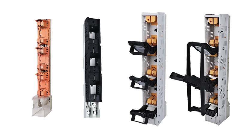
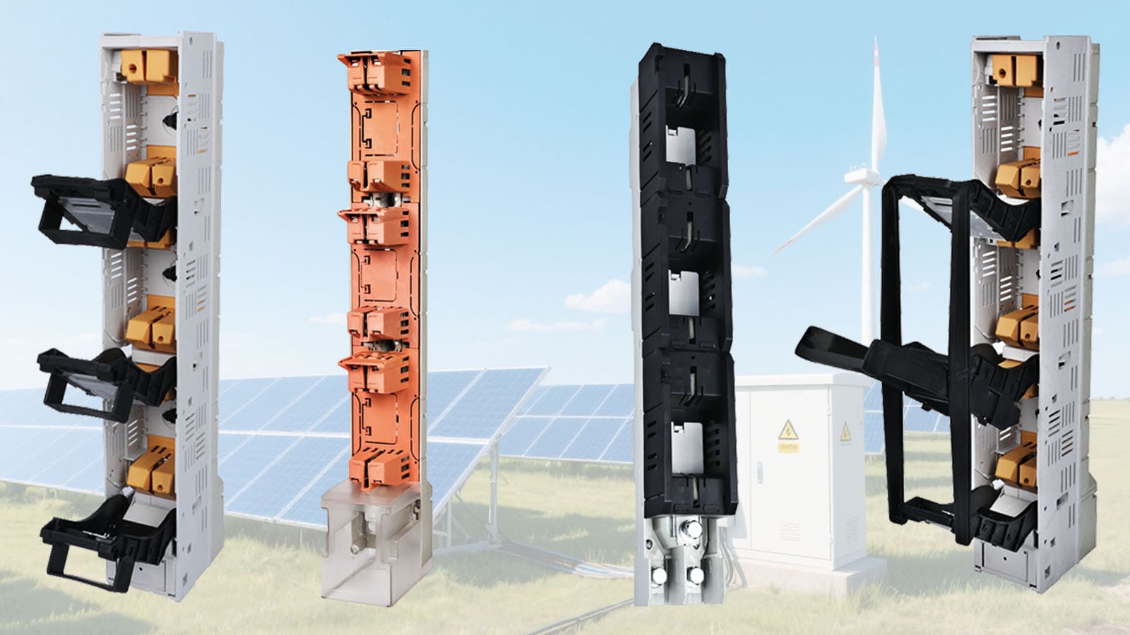
The most common type we manufacture at our factory is the "pan assembly" or "breaker pan" design. This consists of mounting plates with pre-installed busbars configured to accept specific types of circuit breakers that simply snap or bolt into place. The breakers make contact with the busbar automatically, eliminating the need for individual wiring between the power source and each breaker.
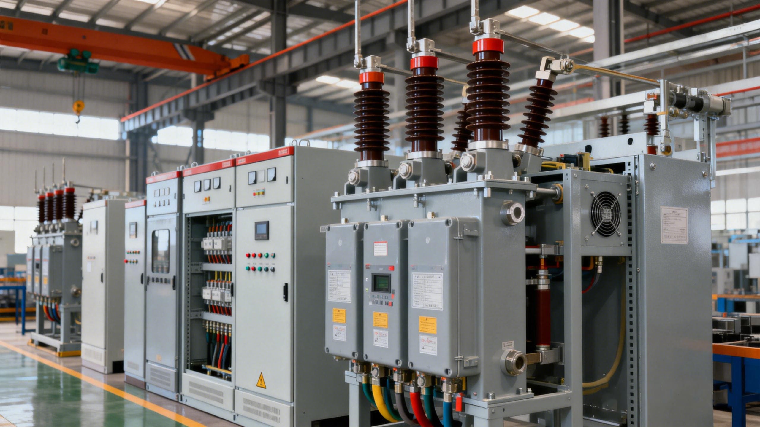
For industrial applications, we produce more robust busbar assemblies2 with higher current ratings and reinforced mounting systems to withstand mechanical stress and vibration. These often include special plating to prevent corrosion in harsh environments.
The evolution of busbar technology has been driven by the need for more efficient power distribution in increasingly compact spaces. Modern busbar assemblies incorporate sophisticated insulation systems3, optimized conductor geometries, and advanced connection technologies that maximize performance while minimizing size.
I recently worked with a panel builder who switched from traditional wiring to our busbar assemblies and reduced their assembly time by nearly 60% while improving the reliability of their products. The standardized nature of busbar assemblies also made their quality control process more consistent and predictable.
What is a circuit breaker bus bar?
Are you confused by the different terms used to describe circuit breaker connections? The relationship between breakers and busbars isn't always clearly explained in product literature.
A circuit breaker bus bar is a specialized conductor designed to distribute power to multiple circuit breakers simultaneously, featuring standardized connection points that align with breaker terminals and allowing for modular installation without individual wiring from the power source to each breaker.

I often explain to customers that the circuit breaker bus bar is essentially the interface between your power source and protection devices. It transforms what would otherwise be a complex web of individual connections into an organized system.
Modern circuit breaker busbars are engineered specifically for the breaker series they're designed to work with. This creates a matched system with several important features:
Circuit Breaker Busbar Characteristics
| Feature | Description | Advantage |
|---|---|---|
| Finger-Safe Design4 | Recessed conductors with limited exposure | Enhanced safety during installation and maintenance |
| Phase Identification | Color-coding or clear markings | Reduces wiring errors |
| Standardized Spacing | Exact alignment with breaker terminals | Quick installation and secure connection |
| Din Rail Integration | Combined mounting system | Stable mechanical support |
| Ampacity Rating5 | Current carrying capacity | Properly sized for connected load |
| Short Circuit Rating6 | Ability to withstand fault currents | Coordination with breaker interrupting capacity |
| IP Protection | Environmental protection level | Suitable for specific installation environments |
The connection between breaker and busbar has evolved significantly. Early designs relied on simple screw terminals, but modern systems use sophisticated contact designs that ensure optimal connection pressure, resist loosening from thermal cycling, and maintain low contact resistance over time.
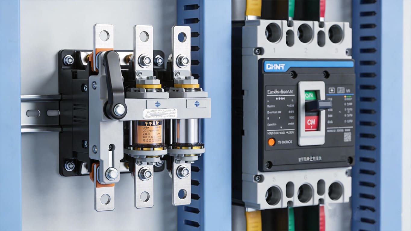
Different breaker types connect to busbars in different ways:
- Plug-in breakers have contact points that automatically connect to the busbar when the breaker is installed in its mounting position
- Bolt-on breakers require manual connection using bolts that secure the breaker terminal directly to the busbar
- Hook-style breakers use a hook-shaped terminal that engages with the busbar and is then secured with a screw
Our manufacturing process includes rigorous testing of these connection points. We subject sample connections to thermal cycling tests that simulate years of operation in just days, ensuring the connection remains stable over the product's lifetime.
I recently helped a customer redesign their panel layout using our circuit breaker busbar system. They were able to fit 30% more breakers in the same enclosure space while actually improving accessibility for maintenance. The modular nature also made future expansion significantly easier as they could add breakers without rewiring the entire panel.
What is the purpose of a busbar?
Do you find yourself wondering why busbars have become so prevalent in modern electrical systems? The shift from traditional wiring to busbar systems represents a fundamental change in distribution philosophy.
The purpose of a busbar is to efficiently distribute electrical power from a single source to multiple loads while reducing voltage drop, minimizing connection points, saving space, improving heat dissipation, simplifying installation and maintenance, and providing better short-circuit withstand capability compared to equivalent wire-based systems.

When I conduct factory tours, I demonstrate the difference between traditional wire-based distribution and busbar distribution to highlight the numerous advantages that busbars bring to modern electrical systems.
Busbars serve multiple purposes that go well beyond simply connecting components:
Key Functions of Busbar Systems
| Function | Technical Benefit | Practical Outcome |
|---|---|---|
| Power Distribution7 | Lower impedance path for current | Reduced energy losses and voltage drop |
| Thermal Management8 | Greater surface area for heat dissipation | Lower operating temperature and extended lifespan |
| Space Optimization | Compact, 3D power distribution | More equipment in limited panel space |
| Fault Tolerance | Higher short-circuit withstand capability | Enhanced safety during fault conditions |
| Maintenance Simplification | Fewer connection points to inspect | Reduced maintenance time and higher reliability |
| Standardization | Consistent installation method | Fewer assembly errors and faster installation |
| Future Expansion9 | Modular connection points | Easier system modifications and upgrades |
The evolution of busbar technology reflects the changing demands of electrical distribution systems. As equipment density increases and available space decreases, the compact nature of busbars becomes increasingly valuable.
Take the example of data centers, where power density is critical. Using traditional wiring methods would require massive cable bundles that create cooling problems and consume valuable space. Modern busbar systems solve these issues by providing more efficient power distribution in a fraction of the space.
In renewable energy applications like solar inverter connections, busbars have become essential for handling the high currents involved. Their superior heat dissipation capabilities allow for more compact equipment designs without sacrificing performance or reliability.
I recently worked with a panel builder who was hesitant to transition from traditional wiring to our busbar systems. They were concerned about the initial investment and learning curve. After implementing busbars in a pilot project, they discovered that the assembly time was reduced by 40%, testing time by 25%, and warranty claims dropped significantly due to the elimination of wiring errors.
For high-current applications, the benefits become even more pronounced. A 400A distribution using traditional cables would require large, difficult-to-bend conductors that are challenging to terminate properly. The equivalent busbar system is more compact, easier to install, and provides better performance characteristics.
What is the best material for a busbar?
Are you uncertain about which material to choose for your busbar system? This common question doesn't have a simple answer, as the "best" material depends on specific application requirements and constraints.
The best busbar material depends on your specific application needs—copper offers superior conductivity (100% IACS) and connection reliability but at higher cost and weight, while aluminum provides significant cost savings (30-50% less) and weight reduction (66% lighter) with adequate performance when properly sized and terminated.

When customers ask me this question at our factory, I always respond with several questions of my own about their specific application before making a recommendation. The choice between busbar materials involves balancing multiple factors.
Here's a comparative analysis of the two most common busbar materials:
Copper vs. Aluminum Busbar Comparison
| Property | Copper | Aluminum | Practical Implication |
|---|---|---|---|
| Electrical Conductivity10 | 100% IACS | 61% IACS | Aluminum requires ~65% larger cross-section |
| Material Cost11 | Higher | 30-50% lower | Significant cost advantage for aluminum |
| Weight | 8.96 g/cm³ | 2.70 g/cm³ | Aluminum is 66% lighter |
| Thermal Expansion | 16.5 ppm/°C | 23 ppm/°C | Copper more stable in temperature fluctuations |
| Connection Stability | Excellent | Good (with proper preparation) | Copper connections typically require less maintenance |
| Corrosion Resistance12 | Good | Moderate (forms insulating oxide) | Copper more forgiving in varied environments |
| Formability | Excellent | Excellent | Both materials work well for complex shapes |
| Thermal Conductivity | 386 W/m·K | 205 W/m·K | Copper dissipates heat better |
| Fatigue Resistance | Excellent | Good | Copper better for vibration exposure |
In practice, the decision often comes down to specific application requirements:
For applications where space is severely constrained, copper's superior conductivity allows for smaller cross-sections, making it the preferred choice despite its higher cost. This is why we typically use copper in our compact distribution blocks and MCB pan assemblies.
For large power distribution systems where weight and cost are significant factors, properly sized aluminum busbars can provide excellent performance at substantially lower cost. Many of our industrial customers opt for aluminum in these applications.
Connection technology is another crucial consideration. Copper forms naturally stable connections with most termination methods. Aluminum requires more careful preparation and specific connection techniques to ensure long-term reliability due to its oxide layer formation and different thermal expansion characteristics.
I recently worked with a solar energy customer who initially specified copper for all their busbar needs based on its superior conductivity. After analyzing their actual requirements, we determined that aluminum was perfectly adequate for their main distribution busbars, while copper remained necessary for certain critical connection points. This hybrid approach reduced their material costs by 35% without compromising system performance.
For applications exposed to harsh environmental conditions (coastal areas, chemical environments, etc.), we often recommend tin-plated copper, which combines excellent conductivity with enhanced corrosion resistance. The additional cost of plating is justified by the extended service life in these challenging settings.
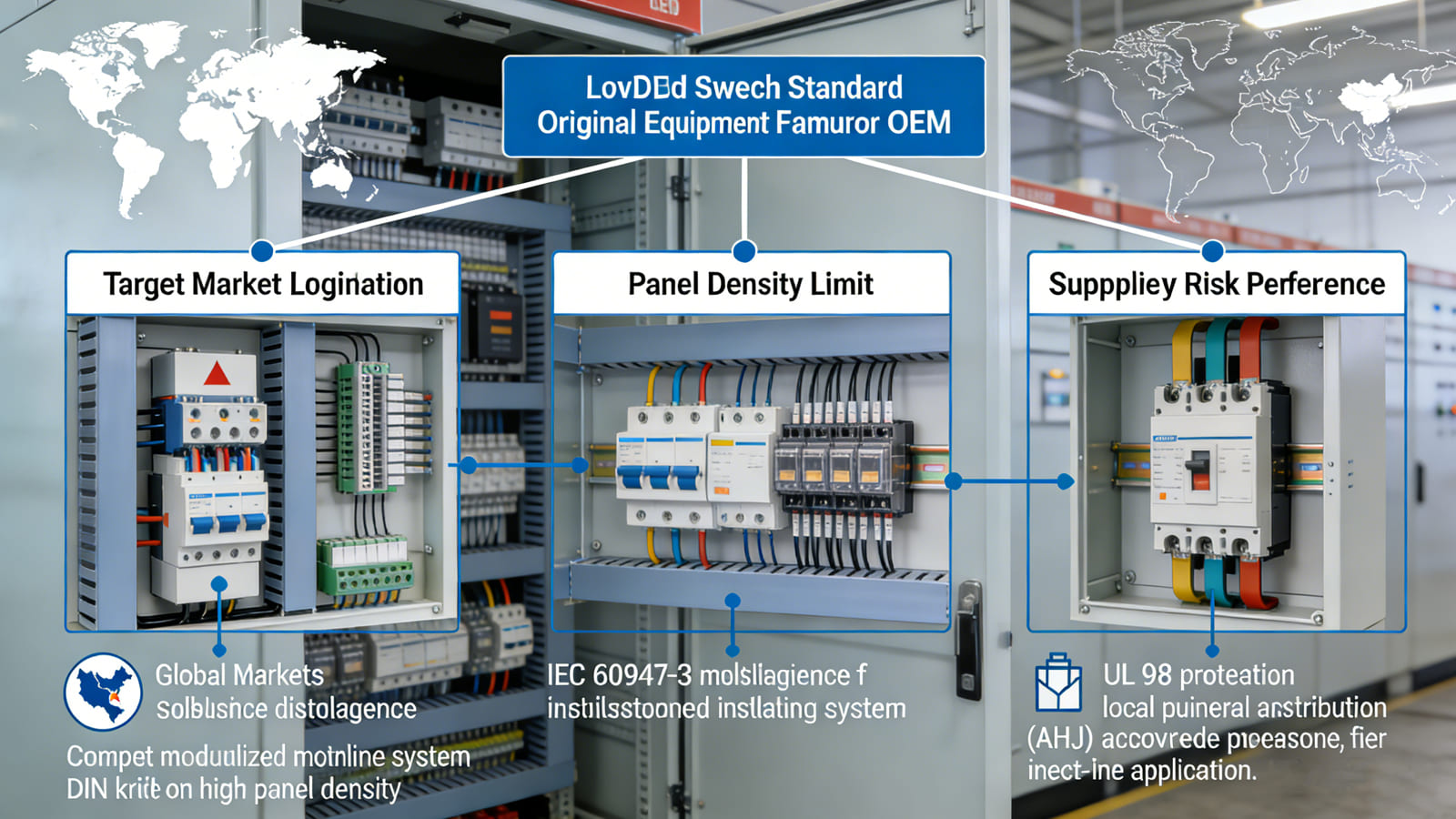
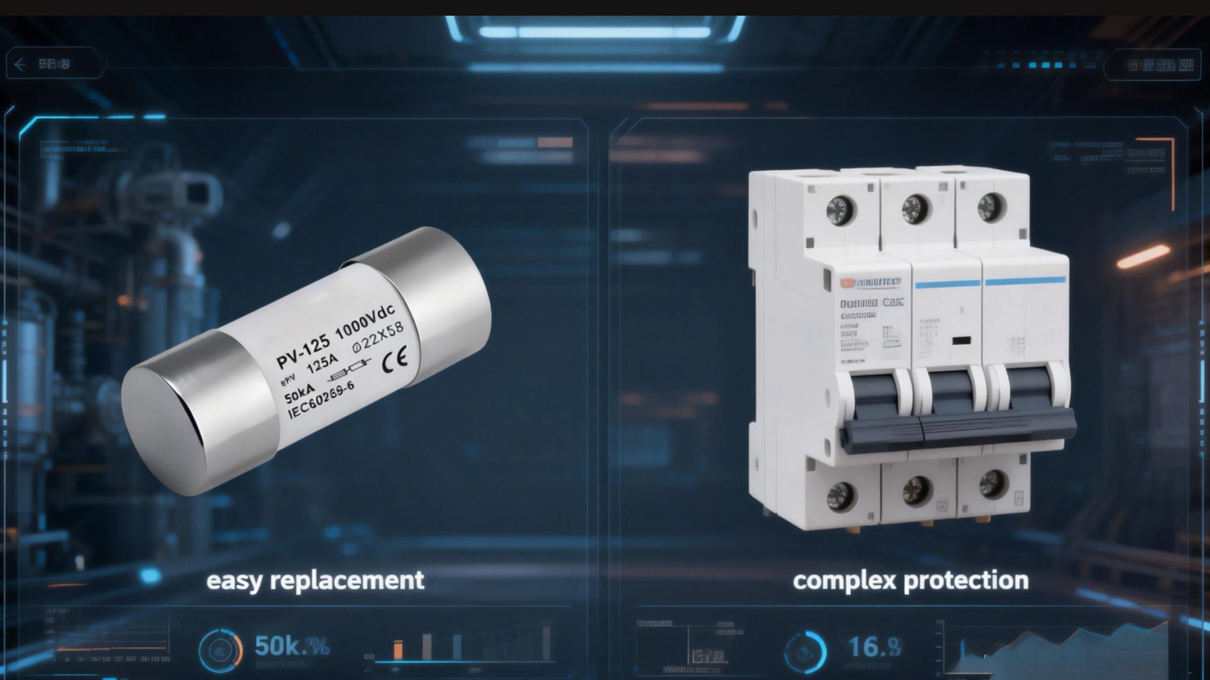
What is the difference between busbar pan assembly and direct feed?
Have you struggled to decide whether to use a busbar pan assembly or direct feed for your electrical distribution system? This common dilemma can significantly impact your panel's performance, reliability, and future flexibility.
A busbar pan assembly distributes power to multiple circuit breakers through a common bus system, allowing for modular installation and easy reconfiguration, while direct feed uses dedicated conductors to connect individual loads directly to the power source, typically for higher current applications or where specialized connections are required.

I often explain this distinction to customers by comparing it to the difference between a power strip (busbar pan) and individual outlet wiring (direct feed) in household terms. Each approach has specific applications where it excels.
These two distribution methods have distinct characteristics that make them suitable for different scenarios:
Busbar Pan Assembly vs. Direct Feed13 Comparison
| Characteristic | Busbar Pan Assembly14 | Direct Feed | Selection Consideration |
|---|---|---|---|
| Installation Time | Faster for multiple breakers | Faster for single large breaker | Number of circuits needed |
| Space Efficiency | Higher density | Lower density | Available panel space |
| Current Capacity | Limited by busbar rating | Limited only by conductor size | Maximum load requirements |
| Flexibility | Easy to add/relocate breakers | Requires rewiring for changes | Future expansion needs |
| Cost Efficiency15 | Lower per-connection cost | Higher per-connection cost | Budget constraints |
| Heat Distribution | Shared thermal mass | Independent thermal paths | Cooling considerations |
| Visual Organization | Standardized appearance | Custom layout | Maintenance preferences |
| Fault Propagation Risk | Potentially affects multiple circuits | Isolated to single circuit | Criticality of loads |
Busbar pan assemblies excel in applications requiring multiple circuits of similar ratings, particularly in commercial and light industrial settings. The modular nature allows for standardized installation and easy future modifications. In our factory, we see customers choosing this option for:
- Commercial distribution panels with numerous similar loads
- Motor control centers where multiple starters share common power inputs
- Lighting control panels where circuit quantities may change over time
- Telecommunications facilities with numerous small, critical loads
Direct feed systems are typically chosen for:
- Very large single loads (e.g., main breakers, large drives)
- Critical circuits requiring dedicated paths
- Specialized applications with unique connection requirements
- Systems with widely varying circuit sizes
- Circuits with specific impedance or voltage drop requirements
I recently worked with a panel builder designing a system for a manufacturing facility. They used our busbar pan assembly for the general distribution section containing multiple 20-60A circuits feeding production equipment. However, for the 250A feed to their critical process controller, they opted for a direct feed using flexible busbars to ensure maximum reliability and minimize impedance.
The decision often comes down to future flexibility needs. If a system's circuit configuration is likely to change frequently, the modular nature of busbar pan assemblies provides significant advantages. For stable, long-term installations where circuits rarely change, direct feed may offer a more optimized solution.
Cost considerations also play a role. While the materials for direct feed may be less expensive for a few circuits, the labor savings of busbar pan assemblies typically make them more economical as the circuit count increases.
Conclusion
Both busbar pan assemblies and direct feed systems have their place in modern electrical distribution. Your choice should match your specific needs for current capacity, flexibility, space efficiency, and future expansion—there's no single "best" solution for all applications.
-
Discover the various circuit breakers that work seamlessly with busbar assemblies for optimal performance and reliability. ↩
-
Explore how busbar assemblies can enhance efficiency and reliability in electrical systems, making them a smart choice for modern applications. ↩
-
Learn about the critical role of insulation systems in preventing short circuits and ensuring safety in electrical setups. ↩
-
Explore how Finger-Safe Design enhances safety and reduces risks during installation and maintenance. ↩
-
Understanding Ampacity Rating is crucial for ensuring electrical systems are properly sized and safe for use. ↩
-
Learn about Short Circuit Rating to ensure your electrical systems can handle fault currents effectively. ↩
-
Explore this link to understand how power distribution in busbar systems minimizes energy losses and enhances efficiency. ↩
-
Learn about thermal management in busbar systems and how it contributes to lower operating temperatures and longer equipment lifespan. ↩
-
Discover how modular connection points in busbar systems facilitate easier modifications and upgrades for future needs. ↩
-
Understanding the conductivity differences can help in selecting the right material for electrical applications. ↩
-
Exploring material costs can guide budget decisions for electrical installations and projects. ↩
-
Learning about corrosion resistance is crucial for ensuring longevity and reliability in various environments. ↩
-
Learn about Direct Feed systems and their advantages for critical circuits and specialized applications. ↩
-
Explore the benefits of Busbar Pan Assembly for efficient electrical installations, especially in commercial settings. ↩
-
Understand how cost efficiency influences the decision-making process in electrical system design. ↩