I often see perfect copper ruined by small layout errors that cause heat, noise, and early trips.
Avoid most busbar faults1 by respecting thermal paths2, tightening to spec, and planning airflow before looks. Careful short-circuit checks, torque discipline, and open layouts prevent most failures.

I learned that readers stay when I share where I failed and fixed. Stay with me while I unpack the most common pitfalls and the simple ways I avoid them.
What are the possible busbar faults?
Loose joints and hot spots worry me more than the metal choice.
Busbar faults include loose joints, overheating, arcing, misaligned phases, and insulation damage3 from vibration or magnetic forces. I prevent these with torque checks, clear spacing, and honest fault-current math.

How I map faults before they happen
I break faults into thermal, mechanical, and electrical. Thermal faults come from poor contact and bad airflow. Mechanical faults come from vibration, movement under fault, and weak supports. Electrical faults come from wrong clearances and weak insulation. I use a simple table to track them on every job.
| Fault type | Cause example | My check | Fix I use |
|---|---|---|---|
| Thermal | Loose bolted joints | Torque wrench to spec | Re-torque and use Belleville |
| Mechanical | Bar shift under stress | Short-circuit force calc | Add supports, respect clearances |
| Electrical | Phase creep/arcing | Measure creepage/clearance | Add barriers, clean edges |
When I start a project, I sit with the single-line and mark where heat can build. I look at bends that trap heat. I check where cables block flow. I also mark where fault forces pull bars. I calculate peak kA and see if the supports hold. If the bar can swing, it will tear insulation. I check creepage in humid sites. Simple habits like cleaning joint faces and using the right paste keep joints cool. I learned that if I assume “it should be fine,” it will not. The time I rushed a retrofit, I skipped one torque check. A week later, we saw darkened copper. Since then, I never skip the wrench.
How to tell if a bus bar is bad?
I trust my nose and thermal camera4 more than a spec sheet.
I spot a bad busbar by looking for discoloration, smelling for burnt insulation, feeling for vibration, and scanning with IR for hot joints. Crack sounds under load also warn me.

The checks I use on live and dead gear
On live gear, I use an IR camera and my senses. On dead gear, I open and inspect. Here is how I break it down.
| Check type | Tool or sense | What I look for | Action I take |
|---|---|---|---|
| Visual | Eyes/flashlight | Dark copper, melted covers | Clean, re-torque, replace |
| Thermal | IR camera | Hot spots at joints | Improve contact, airflow |
| Audible | Ears/stethoscope | Buzzing, cracking under load | Re-seat, tighten supports |
| Tactile | Hand feel (safe) | Vibration or loose hardware | Add supports, torque to spec |
I once walked into a plant and smelled that sweet burnt odor. The IR shot showed one joint 25°C hotter than the rest. The bolts were finger-tight. That small miss could have caused a fire. Now, on every site, I do a quick sniff and scan. If I hear a low buzz that changes with load, I suspect a loose plate. I also press on barriers to feel for movement. In dusty sites, dust on hot bars can char and smell; I clean and watch again. I never trust “looks fine” without a torque check. A bad busbar often hides until it is too late. My simple repeatable checks keep me ahead of failure.
What must a bus bar be capable of handling?
I design bars to handle heat, force, and time, not just amps.
A busbar must handle its continuous current without overheating, withstand peak short-circuit forces, and maintain insulation and mechanical stability over its service life in its environment.

The three capacities I refuse to compromise
I look at three capacities: thermal current rating, short-circuit withstand, and environmental endurance. I put them in a table to keep myself honest.
| Capacity | My focus | Typical check I do |
|---|---|---|
| Thermal current | Temp rise within limits | Measure rise at rated load |
| Short-circuit withstand | Peak and 1s RMS force on supports | Calculate kA, check support spacing |
| Environmental endurance | Humidity, dust, corrosion resistance | Choose plating, barriers, IP rating |
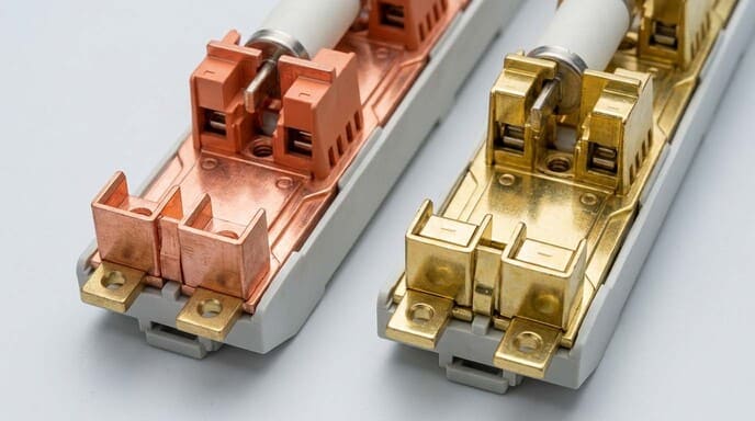
Thermal capacity means the bar stays within rise limits at rated load. I allow for real ambient, not catalog 35°C when I know the room runs hotter. Short-circuit capacity means the bar and its supports do not bend or tear when faults hit. I run fault-current math with realistic utility data. I add supports if the span is long. I do not hide behind “standard practice”; I check the numbers. Environmental endurance is where many fail. In coastal sites, I see white dust on tin-plated bars. I choose silver plate or add covers. In solar combiner boxes, DC arcs are mean; I use more creepage. If I treat each capacity as a promise, the bar will perform. If I skip one, the bar will remind me later.
Electrical Panel Layout Optimization for Heat Dissipation?
Airflow first, beauty second has saved me more than once.
I optimize panel layouts for heat by spacing heat sources, keeping airflow paths open, and using vertical busbars and vented doors to let hot air rise and leave.

How I lay out panels to stay cool
I learned that heat leaves best when I give it a straight path. I use a simple heat map on paper before I touch copper. This table guides me.
| Layout choice | Why I do it | Result I see |
|---|---|---|
| Vertical busbars | Encourage chimney effect | Lower joint temps |
| Staggered breakers | Spread heat sources | Even temperature distribution |
| Open cable alleys | Maintain airflow channels | Better convection |
| Vented doors/top vents | Let hot air escape | Lower internal ambient |
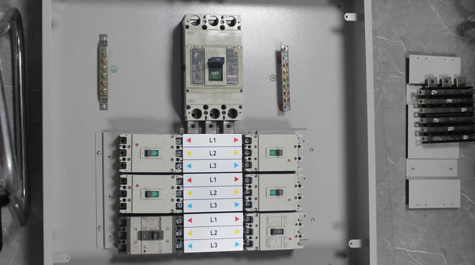
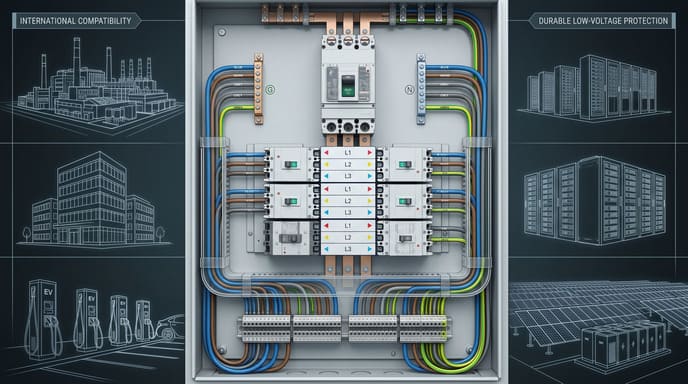
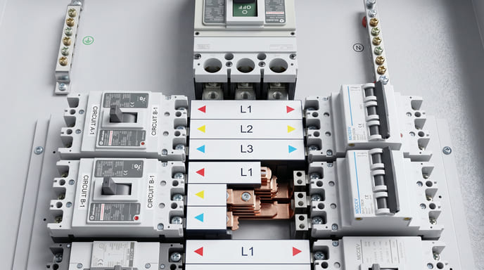
When I designed a DB for a humid plant, I chose vertical color-coded busbars. That let hot air rise and leave. I staggered MCBs so no two large loads sat together. I kept cable alleys clear and wide. I avoided running thick cable bundles over bars. I added vents high on the door. During tests, the hottest joint stayed under 70°C at full load. Without these choices, I would have seen 10°C more. I also learned to put sensors where heat might build. A small wireless probe near the top tells me if my plan works. If it runs hot, I add a small fan. But I always start with passive paths. Pretty symmetry is nice, but a cool panel is safer and lasts longer.
Conclusion
Respect physics, torque every joint, and let heat and forces flow where you planned; do that and busbar problems almost vanish.
-
Understanding busbar faults can help you avoid costly mistakes and ensure system reliability. ↩
-
Exploring thermal paths will enhance your knowledge of heat management in electrical systems. ↩
-
Understanding insulation damage can help you maintain system integrity and safety. ↩
-
Using a thermal camera can enhance your inspection process and identify issues early. ↩