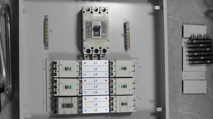
When designing electrical panels, I often see confusion about ground and neutral connections. Combining them seems logical for simplicity, but could this seemingly small detail create dangerous conditions that put lives and equipment at risk?
Ground and neutral can be connected to the same bus bar only at the main service entrance or at the first means of disconnect in a system. In all other locations like subpanels or downstream distribution points, ground and neutral must be kept separate to prevent dangerous current paths, equipment damage, and potential shock hazards.

This question comes up regularly when I talk with panel builders and electrical contractors. The answer isn't just about technical compliance—it's fundamentally about safety. Let me explain the critical differences between these configurations and why making the right choice matters for your electrical systems.
Is it okay to put neutral and ground together?
Have you ever wondered why some panels have separate bars for ground and neutral connections while others combine them? This seemingly small detail can make a crucial difference in electrical safety.
Neutral and ground should only be connected together at one point in the electrical system—typically at the main service entrance. At all other points, they must remain separate to prevent dangerous parallel return paths, ground loops, and potential shock hazards.

I've seen many situations where this principle was misunderstood, leading to dangerous installations. The rules about neutral-ground bonding aren't arbitrary—they're based on fundamental electrical safety principles that protect both people and equipment.
The key concept is the "single point of bonding." In any properly designed electrical system, there should be exactly one location where ground and neutral connect. This creates a controlled reference point for the entire system's voltage potential.
Where Neutral-Ground Bonding1 is Permitted:
| Location | Bonding Status | Reasoning |
|---|---|---|
| Main Service Entrance | Bonded | Establishes system reference point and fault path |
| First Disconnect Means | Bonded | Alternative service entrance configuration |
| Separately Derived System | Bonded | Creates new reference point (e.g., transformer secondary) |
| Generator with Transfer Switch | Special Case | Depends on transfer switch type and configuration |
For main service entrances, this bonding is implemented through a main bonding jumper2 that connects the neutral bus to the ground bus and enclosure. This connection provides the essential return path for fault current to trip protective devices.
I recently inspected a factory installation where the team had mistakenly bonded neutral and ground in both the main panel and a subpanel. This created multiple return paths for neutral current, allowing it to flow through equipment grounding conductors3 and creating subtle but dangerous voltage potentials on supposedly "grounded" equipment. We immediately corrected this to prevent potential injuries.
Remember: this distinction becomes even more crucial in systems with sensitive electronic equipment, where improper grounding can lead to data corruption, equipment damage, and mysterious performance issues that are difficult to diagnose.
Do neutral and ground need to be separated?
Are the requirements to separate neutral and ground just bureaucratic rules, or is there real science behind them? Many electricians follow these rules without fully understanding why they matter so much.
Neutral and ground must be separated at all points in the electrical system except at the main service entrance. This separation prevents neutral current from flowing through grounding conductors and equipment frames, which would create shock hazards and defeat the protective purpose of the grounding system.

When I explain this concept to customers designing distribution systems, I use a simple water analogy: think of electricity as water that always needs to return to its source. The neutral wire is the designated "pipe" for this return flow during normal operation. The ground wire is a safety "pipe" that should remain dry unless there's a fault.
If you connect these "pipes" together at multiple points, you create parallel paths where current can flow unpredictably—some through the intended neutral path and some through the safety ground path. This defeats the entire purpose of having a separate safety system.
The technical reasons for separation include:
Consequences of Improper Neutral-Ground Connections
| Issue | Technical Explanation | Practical Impact |
|---|---|---|
| Parallel Current Paths4 | Creates multiple return paths for neutral current | Unbalanced loading and overheating of conductors |
| Elevated Ground Potential5 | Ground conductors carry regular load current | Shock risk from "grounded" equipment and surfaces |
| Nuisance Tripping6 | Ground fault current sensors detect normal current as faults | System reliability issues and unwanted shutdowns |
| EMI/Noise Problems | Ground loops create noise in sensitive equipment | Data errors, signal corruption, equipment malfunction |
| Hampered Fault Detection | Diluted fault currents may not trip protection devices | Safety systems fail to operate when needed |
A key concept to understand is that the neutral conductor regularly carries current during normal operation. If neutral and ground are connected at multiple points, some of this normal return current will flow through ground wires, chassis, and other grounded components—creating voltage differences between "grounded" items that should be at the same potential.
During my factory visits, I sometimes use a voltage meter to demonstrate this principle to skeptical customers. By measuring between grounded equipment in systems with improper bonding, I can show measurable voltages that shouldn't exist—voltages that could potentially cause shocks.
The exception at the service entrance exists specifically to establish a reference point and to ensure that fault currents have a path back to the source to enable overcurrent devices to trip when needed.
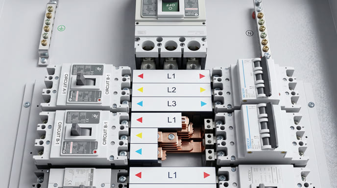
Can you double up wires on the bus bar?
Have you faced the challenge of limited space on a bus bar when you have numerous circuits to connect? The temptation to double up wires under single terminals is common, but is it actually safe?
Double-up connections on bus bars are only permitted when the terminal is specifically listed and marked for multiple conductors. Most standard terminal screws are designed and tested for just one wire, and improper doubling can lead to loose connections, overheating, and potential fire hazards.

I frequently inspect electrical panels where installers have doubled up neutrals or grounds under a single terminal. This practice, while tempting from a convenience standpoint, often violates both code requirements and manufacturer specifications.
The issue is fundamentally about connection integrity. Each terminal on a bus bar is designed with specific mechanical and electrical characteristics that are validated during product testing and certification.
Bus Bar Terminal Requirements
| Terminal Type | Multiple Wire Capability | Identification | Common Applications |
|---|---|---|---|
| Standard Screw | Usually not permitted | No special marking | Basic panels and low-cost equipment |
| Dual-Rated Terminal | 2 wires of specified gauge | Marked with "2" or dual wire symbol | Higher-end distribution equipment |
| High-Capacity Terminal | Varies by design | Specific marking and instructions | Industrial equipment and high-ampacity systems |
| Pressure Plate Design | Often allows multiple connections | Terminal area markings | Premium distribution equipment |
When multiple conductors are placed under a terminal not designed for that purpose, several problems can occur:
- Uneven pressure distribution may leave one wire loose while the other seems tight
- Different wire sizes compound the problem, with smaller wires potentially becoming loose over time
- Thermal cycling from load changes can gradually loosen the connection
- Different metals (if using copper and aluminum) can cause galvanic issues and accelerated loosening
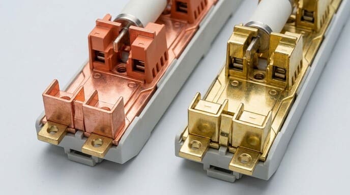
In our busbar production at Fuspan, we specifically design and test certain models for multiple wire terminations7. These feature wider terminals, specialized pressure plates, or specific geometries that ensure reliable contact with multiple conductors. These are clearly marked to indicate multiple-wire capability.
For standard installations where doubling up isn't permitted but additional connections are needed, I recommend these alternatives:
- Use a larger bus bar with more connection points
- Add a supplementary bus bar specifically for the additional connections
- Use jumper wires from a single terminal to nearby secondary connection points
- For neutrals, consider using branch circuit rated connectors before connecting to the bus
Remember that proper torquing of connections8 is equally important. Even a properly rated multi-wire terminal will fail if not tightened to the manufacturer's specified torque value.
What happens if neutral touches ground in a subpanel?
Have you wondered about the real-world consequences of neutral-ground contact in a subpanel? This scenario occurs more often than you might think, whether through improper installation or gradual system deterioration.
If neutral touches ground in a subpanel, part of the normal return current will flow through ground wires and connected equipment frames. This creates shock hazards, interferes with ground fault protection, potentially damages sensitive equipment, and violates electrical codes designed to prevent these precise dangers.

I've investigated numerous electrical problems where an improper neutral-ground connection was the root cause. In one industrial facility, workers reported intermittent shocks from machine frames. Our investigation revealed that a stray wire strand from a neutral conductor was making contact with the panel enclosure, creating a parallel path for neutral current through the grounding system.
The technical effects of neutral-ground contact in a subpanel include:
Effects of Neutral-Ground Contact in Subpanels
| Effect | Technical Explanation | Safety Implication |
|---|---|---|
| Circulating Currents9 | Normal neutral current partially diverts through ground paths | Energizes supposedly "dead" grounding system |
| Elevated Touch Voltage | Ground-referenced equipment rises above zero potential | Shock risk even during normal operation |
| Reduced GFCI Effectiveness10 | Leakage current sensors confused by normal current flow | Protection devices may not trip when needed |
| Electrical Noise11 | Ground loops create magnetic fields and induced currents | Electronic equipment malfunction or damage |
| Code Violation | Specific violation of NEC 250.142(B) | Installation fails inspection and insurance requirements |
The severity of these effects depends on several factors, including the resistance of the unintended connection, the load current flowing through the circuit, and the overall system configuration. Even a high-resistance contact between neutral and ground can create problems, especially with sensitive electronic equipment.
Let's consider a practical scenario: In a 240/120V system, a neutral-ground connection in a subpanel might allow 2-3A of normal current to flow through the equipment grounding conductor. This creates a voltage drop that could easily produce a 1-2V potential difference between the panel's "ground" and true earth ground. While this might not sound significant, it's more than enough to cause:
- Mysterious electronic equipment failures or data errors
- Perceptible shocks under the right contact conditions
- Accelerated corrosion in grounded metal components
- False alarms or failures in sensitive monitoring equipment
The insidious nature of this problem is that the system appears to function normally—lights work, appliances run—while the safety system is compromised. Often, the issue only becomes evident when a ground fault occurs and doesn't clear properly, or when someone experiences an unexpected shock.
Conclusion
Ground and neutral should only connect at the service entrance—never in subpanels or downstream equipment. This seemingly small detail is fundamental to electrical safety, preventing dangerous current paths, equipment damage, and potential shock hazards in your distribution systems.
-
Understanding Neutral-Ground Bonding is crucial for safety and equipment integrity. Explore this link to learn more about its significance. ↩
-
The main bonding jumper is vital for safety in electrical systems. Discover its function and importance in this informative resource. ↩
-
Equipment grounding conductors are essential for safety. Learn how they function to protect your electrical systems and equipment. ↩
-
Understanding Parallel Current Paths is crucial for preventing unbalanced loading and overheating, ensuring safety and efficiency in electrical systems. ↩
-
Exploring Elevated Ground Potential helps in recognizing shock risks and improving safety measures in electrical installations. ↩
-
Learning about Nuisance Tripping can enhance system reliability and prevent unwanted shutdowns, crucial for operational efficiency. ↩
-
Explore this resource to understand the best practices and ensure reliable connections in your busbar applications. ↩
-
Discover the importance of proper torquing to prevent failures and ensure the longevity of your electrical connections. ↩
-
Understanding circulating currents can help you prevent safety hazards and ensure proper electrical system functioning. ↩
-
Exploring GFCI effectiveness can enhance your knowledge of electrical safety and protection devices. ↩
-
Learning about electrical noise can help you protect sensitive equipment and improve system reliability. ↩