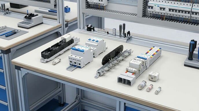
Many electrical panels I've inspected contain a mix of protection devices that confuse even experienced contractors. This confusion often leads to improper device selection, creating safety risks and causing expensive downtime when systems fail under fault conditions.
MCB stands for Miniature Circuit Breaker, while MCCB stands for Molded Case Circuit Breaker. Both are automatic protection devices that interrupt electrical circuits during abnormal conditions, but they differ significantly in design, application range, and protection capabilities based on their construction and operating principles.

When I visit manufacturing facilities or commercial buildings, I often spot protection devices that aren't properly matched to their applications. This mismatch stems from a fundamental misunderstanding of what these devices are designed to do and how they differ. Let's explore the crucial differences that will help you make better selection decisions.
What is the Rating of MCB MCCB?
During facility assessments, I frequently discover undersized protection devices struggling with loads they weren't designed to handle. This common mistake compromises safety and often results in nuisance tripping that interrupts critical operations.
MCBs typically have current ratings from 0.5A to 125A with breaking capacities of 6-10kA (up to 25kA for special types). MCCBs offer much broader ratings, ranging from 16A to 1600A with breaking capacities from 16kA to 100kA. MCCBs also feature adjustable settings for current, time delays, and often include electronic trip units for advanced protection functions.

Through my years of helping clients select the right protection devices, I've learned that understanding the complete rating system is essential for proper application. Let's examine the comprehensive rating factors that determine proper device selection.
Comprehensive Rating System and Selection Criteria
When I work with panel builders and electrical contractors, I emphasize that proper device selection requires understanding multiple rating parameters beyond just nominal current. This broader perspective helps prevent both safety issues and unnecessary expenses.
I recently consulted with a manufacturing facility that experienced repeated breaker trips during motor startups. They had installed standard MCBs on all circuits, including their motor loads. After analyzing their system, I discovered their motor inrush currents were creating momentary demands far exceeding the MCBs' magnetic trip thresholds. By replacing these with properly rated MCCBs1 that offered adjustable magnetic trip settings, we eliminated the nuisance tripping while maintaining proper protection.
The comprehensive rating system for both devices includes:
| Rating Parameter | MCB Range | MCCB Range | Selection Implications |
|---|---|---|---|
| Current Rating (In) | 0.5A to 125A | 16A to 1600A | Determines continuous current handling capability |
| Breaking Capacity (Icu)2 | 6kA to 25kA | 16kA to 100kA | Must exceed maximum potential fault current |
| Operating Voltage | Up to 440V AC | Up to 1000V AC | Must match system voltage |
| Trip Curve Classification3 | B, C, D, K, Z types | Adjustable settings | Should match load characteristics |
| Pole Configuration | 1, 1+N, 2, 3, 3+N, 4 | 2, 3, 4 | Determined by system type (single/three-phase) |
| Terminal Capacity | Typically up to 35mm² | Up to 300mm² | Must accommodate required conductor size |
| Temperature Compensation | Fixed derating factors | Often adjustable | Affects performance in extreme environments |
| Frequency Rating | Typically 50/60Hz | 50/60Hz (some DC rated) | Critical for special applications |
Breaking capacity deserves special attention, as it's often misunderstood. This rating indicates the maximum fault current a device can safely interrupt without catastrophic failure. I've seen installations where the available fault current far exceeded the breaking capacity of the installed MCBs, creating a serious safety hazard. In one commercial building, we calculated a potential fault current of 18kA at a distribution board equipped with standard 10kA MCBs. This discovery prompted an immediate retrofit with appropriate MCCBs to ensure safe fault interruption.
The trip curve classification is equally important, particularly for loads with special characteristics. Standard "C" curve MCBs trip magnetically at 5-10 times rated current, which works well for general purposes but can cause nuisance tripping with high inrush equipment like transformers or motors. In these applications, "D" curve MCBs (tripping at 10-20 times rated current) or adjustable MCCBs provide much better performance. I always recommend analyzing actual load profiles before finalizing protection device specifications.
What is the Difference Between a Breaker and a MCCB?
Clients often use "breaker" as a generic term, not realizing that selecting the wrong breaker type can lead to inadequate protection or unnecessary expense. This confusion creates risks in their electrical systems that could easily be avoided.
A standard breaker (often referring to MCB) is designed for lower current applications (up to 125A) with limited fault current interruption capacity, fixed trip settings, and DIN rail mounting. An MCCB handles higher currents (up to 1600A), offers greater fault interruption capacity, features adjustable protection settings, and is panel-mounted. MCCBs also provide more sophisticated protection options like ground fault and electronic trip units.

The structural and functional differences between these devices directly impact their application in electrical distribution systems. Understanding these distinctions helps ensure proper protection at every level.
Structural and Functional Differences
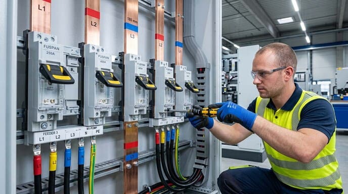
Through my work with switchgear manufacturers and industrial clients, I've gained hands-on experience with the internal construction differences that give these devices their distinct capabilities. These structural differences directly translate to functional advantages in specific applications.
Last year, I helped a food processing plant upgrade their electrical distribution system. Their old panel used standard breakers throughout, including for their main incoming supply. Upon inspection, I discovered their calculated fault current4 exceeded 35kA – far beyond their breakers' capabilities. We replaced their main and feeder protection with properly rated MCCBs, creating a robust system that could safely interrupt the maximum possible fault current. The improved reliability eliminated the sporadic outages they had previously experienced during power fluctuations.
The key structural and functional differences include:
| Feature | Standard Breaker (MCB) | MCCB | Practical Impact |
|---|---|---|---|
| Operating Mechanism | Simple toggle mechanism | Heavy-duty operating mechanism | MCCBs withstand more operational cycles and higher mechanical stresses |
| Arc Extinction | Basic arc chutes | Advanced arc chambers with multiple plates | MCCBs provide superior arc containment during high-current faults |
| Terminal Construction | Designed for smaller conductors | Heavy-duty terminals for large cables/busbars | MCCBs accommodate the larger conductors needed for high-current applications |
| Trip Unit Technology | Fixed thermal-magnetic elements | Interchangeable thermal-magnetic or electronic units | MCCBs offer customizable protection characteristics |
| Contact Design | Basic contact system | Advanced contact materials and pressure systems | MCCBs maintain better performance under repeated fault interruptions |
| Housing Construction | Plastic housing with limited strength | Reinforced molded case designed for higher pressures | MCCBs contain more severe fault energy without rupture |
| Protection Functions | Basic overload and short circuit | Multiple protection functions (overload, short-circuit, ground fault, etc.) | MCCBs provide more comprehensive system protection |
| Selective Coordination | Limited coordination capabilities | Advanced time/current coordination features | MCCBs enable proper selective coordination5 in tiered systems |
These structural differences create distinct performance profiles that determine proper application. For distribution boards feeding final circuits in commercial buildings, standard MCBs typically provide sufficient protection while optimizing cost. However, for main incoming supplies, large motor circuits, or in high fault-current environments, the robust construction and advanced features of MCCBs are essential for safe, reliable operation.
I've observed that selective coordination is particularly important in critical facilities like hospitals or data centers, where isolating faults to the closest protective device prevents unnecessary outages. In these applications, MCCBs with adjustable time delays and electronic trip units allow precise coordination that standard breakers simply cannot provide.
What is the Difference Between a Fuse and a MCB?
When I started in this industry, many panels still used fuses extensively. Today, I primarily encounter them in specialized applications, though clients still ask about the tradeoffs between fuses and MCBs when planning new installations.
A fuse is a sacrificial device containing a metal element that melts when excessive current flows, creating a permanent open circuit that requires replacement. An MCB is a resettable mechanical device that trips under fault conditions and can be restored to service by simply resetting the handle. MCBs offer consistent trip characteristics over time, visual status indication, and simultaneous tripping of multiple poles, unlike fuses.

Both devices provide circuit protection, but their operational differences significantly impact system maintenance, downtime, and overall protection strategy.
Operational Advantages and Disadvantages
Through numerous installation projects and maintenance scenarios, I've experienced the practical implications of choosing between fuses and MCBs. Each technology has specific strengths that make it more suitable for certain applications.
I recall one manufacturing facility that operated with traditional fuse protection6 for decades. After a power surge caused multiple fuse failures across their facility, production was halted for nearly four hours while maintenance personnel located and replaced dozens of blown fuses – some in difficult-to-access locations. Following this costly downtime incident, we converted their distribution system to MCBs. Six months later, when a similar event occurred, operators simply reset the tripped breakers and resumed production within minutes.
The key operational differences include:
| Aspect | Fuse | MCB | Practical Implication |
|---|---|---|---|
| Operation After Fault | Must be replaced | Can be reset | MCBs minimize downtime and eliminate replacement costs |
| Trip Indication | Requires inspection to confirm | Visual handle position | MCBs provide clear fault indication |
| Trip Curve Consistency | Deteriorates with age and previous events | Remains consistent throughout life | MCBs deliver more predictable protection |
| Speed of Operation | Very fast (<1ms) for high faults | Typically 3-5ms for high faults | Fuses offer superior protection for sensitive electronics |
| Breaking Capacity | Very high (up to 200kA) | Limited (typically up to 25kA) | Fuses excel in high fault current environments |
| Selectivity | Excellent natural selectivity | Requires careful coordination | Fuses can provide better discrimination in some systems |
| Multiple Pole Tripping | Independent operation | Common trip mechanism | MCBs ensure all poles open simultaneously |
| Tamper Resistance | Can be replaced with oversized fuse | Settings generally fixed | Fuses are more susceptible to improper replacement |
| Current Limitation | Excellent current limiting effect | Limited current limiting ability | Fuses provide better downstream protection |
| Cost Comparison | Lower initial cost, ongoing replacement cost | Higher initial cost, no replacement cost | MCBs typically have lower total cost of ownership |
The superior current limitation7 of fuses makes them particularly valuable in semiconductor protection applications, where I still recommend them despite the maintenance disadvantages. The extremely fast response of properly rated fuses provides protection that MCBs simply cannot match for sensitive electronics.
Conversely, in most commercial and light industrial applications, the operational advantages of MCBs8 – particularly their resettability and consistent performance – make them the preferred choice. The ability to quickly restore service without replacement parts provides significant operational advantages, especially in facilities without dedicated electrical maintenance personnel.
Which is Better Fused Switch or MCCB?
This question frequently arises when clients are designing main distribution points or considering replacements for aging switchgear. The decision impacts not just protection but also operational procedures and maintenance requirements.
Neither fused switches nor MCCBs are universally "better" – each excels in specific applications. Fused switches offer superior current limitation, higher interruption ratings, and often lower costs for very high current applications. MCCBs provide adjustable protection settings, resettability, built-in isolation, and lower maintenance requirements. The optimal choice depends on specific application requirements, fault levels, and operational preferences.

I've helped clients implement both solutions successfully by focusing on their specific requirements rather than general preferences. Let's examine the factors that should drive this important decision.
Application-Specific Selection Criteria
In my consulting work with industrial clients and panel builders, I emphasize that the choice between fused switches and MCCBs should be based on a systematic evaluation of technical requirements and operational priorities.
Recently, I assisted a solar farm developer with their protection strategy for combiner boxes. After analyzing their specific needs – including high DC fault currents and the remote location of equipment – we selected fused disconnect switches9 despite their higher maintenance requirements. The superior current limitation10 and higher interruption ratings of fuses provided critical protection for their expensive inverter equipment, while the visible break of the switch mechanism gave maintenance teams confidence during service procedures.
The key selection factors include:
| Selection Factor | Fused Switch Advantage | MCCB Advantage | Application Consideration |
|---|---|---|---|
| Current Limitation | Superior limitation of let-through energy | Limited current limiting ability | Critical for protecting sensitive downstream equipment |
| Interruption Rating | Very high ratings economically achievable | Limited by mechanical construction | Important in high fault current environments |
| Coordination | Excellent natural coordination with fuse selectivity | Requires careful electronic coordination | Simpler coordination in complex distribution systems |
| Visible Break | Clear physical separation | Often requires additional isolators | Important for maintenance safety |
| Adjustability | Fixed characteristics based on fuse selection | Adjustable trip settings | Valuable for fine-tuning protection |
| Maintenance | Requires fuse replacement after operation | Resettable with periodic testing | Consider available maintenance resources |
| Remote Operation | Requires motorized switches | Available with motor operators | Important for automated systems |
| Environmental Sensitivity | Less sensitive to ambient temperature | Requires derating at high temperatures | Consider installation environment |
| Physical Size | Often larger at lower ratings, smaller at very high ratings | More compact at low/medium ratings | Important where space is constrained |
| Installation Flexibility | Requires specific orientation | More flexible mounting options | Consider installation constraints |
When considering cost factors, the analysis becomes more complex. At lower ratings (up to about 250A), MCCBs typically offer lower total cost of ownership11 due to their elimination of replacement parts and reduced maintenance requirements. At very high ratings (above 800A), fused switches often become more economical due to the significantly higher cost of high-capacity MCCBs.
The nature of the protected load also influences the optimal choice. For motor loads, MCCBs with adjustable magnetic trip settings can be precisely tuned to accommodate startup inrush while maintaining tight protection during running conditions. For transformer protection, the excellent current limitation of fuses provides superior protection against secondary short circuits.
I always recommend considering the available fault current at the installation point. In applications where the available fault current exceeds 50kA, fused switches often provide a more economical solution for safe interruption. However, in modern buildings with moderate fault levels, the operational advantages of MCCBs typically outweigh the performance benefits of fused solutions.
Conclusion
Understanding MCB and MCCB differences is essential for proper electrical system protection. While MCBs excel in final distribution applications up to 125A, MCCBs provide robust protection for higher currents with greater adjustment capabilities. Your specific requirements—including load characteristics, fault levels, and operational priorities—should guide your selection for optimal safety and reliability.
-
MCCBs offer adjustable settings and higher breaking capacities, making them essential for certain applications. Learn more about their benefits here. ↩
-
Understanding Breaking Capacity (Icu) is crucial for ensuring safety in electrical installations. Explore this link to learn more about its significance. ↩
-
Trip Curve Classification is vital for selecting the right protection devices. Discover its impact on performance and safety in this resource. ↩
-
Understanding fault current is crucial for designing safe electrical systems that can handle unexpected surges effectively. ↩
-
Learn how selective coordination minimizes outages in critical facilities, ensuring uninterrupted operations during faults. ↩
-
Learning about fuse protection can provide insights into its applications and benefits in various electrical systems. ↩
-
Understanding current limitation is crucial for selecting the right protection device, especially in sensitive applications like semiconductors. ↩
-
Exploring the operational advantages of MCBs can help you make informed decisions for efficient electrical systems. ↩
-
Explore the benefits of fused disconnect switches for solar farms, especially in high DC fault current scenarios, to enhance protection strategies. ↩
-
Understanding current limitation is crucial for selecting the right protection device, especially for sensitive equipment in critical applications. ↩
-
Learn about the cost implications of MCCBs and fused switches to make informed decisions based on long-term financial impacts. ↩