Every electrician I've worked with has faced that moment of frustration – staring at a tangle of wires inside a distribution panel, wondering how to install numerous circuit breakers efficiently without compromising safety or future maintenance access.
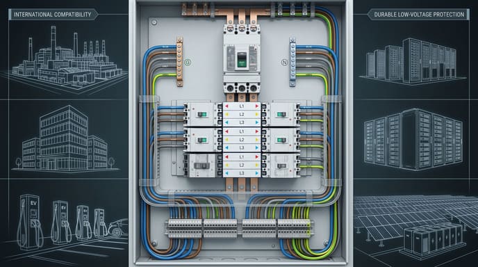
An MCB panel assembly is a pre-fabricated electrical distribution unit centered around Miniature Circuit Breakers (MCBs). It combines a metal or plastic enclosure with integrated busbar systems, MCB mounting rails, and terminal connections designed to simplify installation, ensure proper electrical connections, and provide overcurrent protection for multiple circuits.
Throughout my years supplying electrical components to panel builders, I've witnessed a significant evolution in how MCB panels are assembled and integrated into electrical systems. The days of time-consuming, on-site wire-by-wire assembly are increasingly being replaced by more efficient pre-assembled solutions. Let me explain why this matters for your projects.
What is a MCB Panel?
When I first enter a client's facility, I often notice outdated distribution panels that create bottlenecks in their operations – difficult to modify, time-consuming to maintain, and sometimes posing safety risks due to improvised solutions.
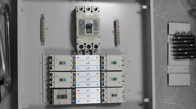
An MCB panel is a protective enclosure containing multiple Miniature Circuit Breakers arranged in an organized layout with standardized DIN rail mounting. It includes a busbar system for power distribution, terminal blocks for outgoing connections, and proper insulation barriers. This assembly serves as a centralized point for circuit protection and electrical distribution in residential, commercial, or industrial applications.

The heart of a well-designed MCB panel lies in its systematic organization and proper integration of components. This isn't just about aesthetics – it directly impacts functionality, safety, and future serviceability.
Key Components and Design Considerations
In my factory tours with clients, I often demonstrate how a properly designed MCB panel assembly1 is much more than just a box with circuit breakers. The integrated design approach makes a tremendous difference in both installation efficiency and long-term reliability.
For example, last month I worked with a factory that was expanding their production line. Their existing electrical panels used traditional wire-by-wire connections to feed their MCBs, resulting in cluttered panels that were difficult to troubleshoot and modify. By switching to a modular MCB panel assembly2 with integrated busbars, they reduced installation time by nearly 65% and created a system that could be easily expanded as their production needs grew.
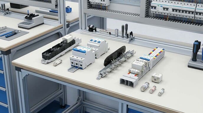
A properly engineered MCB panel assembly typically includes:
| Component | Function | Design Considerations |
|---|---|---|
| Enclosure | Physical protection, environmental isolation | IP rating appropriate for environment, adequate size for heat dissipation |
| DIN Rails | Standardized mounting for MCBs and other devices | Proper spacing for heat dissipation, secure mounting to enclosure |
| Main Incoming Supply | Connection point for power source | Properly sized for total load, accessible for maintenance |
| Busbar System | Power distribution to multiple MCBs | Current capacity rating, insulation, secure mounting, phase arrangement |
| MCBs | Circuit protection for individual circuits | Appropriate current ratings, breaking capacity, terminal size |
| Neutral/Earth Bars | Connection points for neutral and earth conductors | Adequate terminal points, proper sizing, secure mounting |
| Terminal Blocks | Connection points for outgoing circuits | Appropriate size for conductors, logical arrangement, labeling |
| Cable Management | Organized routing of conductors | Adequate space, strain relief, separation of circuits |
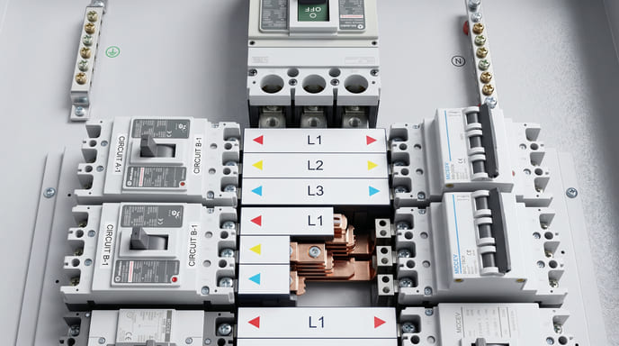
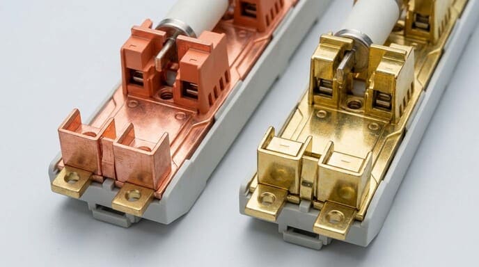
The integration of these components requires careful consideration of both electrical requirements and practical aspects of assembly and maintenance. I've found that manufacturers who focus on the quality of interconnection systems – particularly the busbar design3 – tend to produce panels that not only install faster but also provide superior long-term reliability.
What Does MCB Mean?
Early in my career, I noticed confusion among some clients about different circuit protection terminology. Understanding the specific advantages of MCBs helps clarify why they're the preferred choice for modern panel assemblies.
MCB stands for Miniature Circuit Breaker, a compact electrical protection device that automatically interrupts current flow during overload or short circuit conditions. Unlike traditional fuses, MCBs can be reset after tripping and provide consistent trip characteristics throughout their lifespan. They typically handle currents up to 100A and are designed to protect cables and equipment in low-voltage electrical installations.

The development of reliable MCBs has transformed electrical protection strategies across all sectors, offering advantages that earlier protection methods simply couldn't match.
MCB Operating Principles and Classifications
Throughout my years working with electrical contractors and panel builders, I've noticed that understanding the inner workings of MCBs helps them make better decisions about panel design and circuit protection strategies.
MCBs operate using a dual-protection mechanism4 that responds to different fault conditions. The thermal element (a bimetallic strip) provides protection against moderate but persistent overloads by bending when heated by excessive current, eventually triggering the trip mechanism. The magnetic element (a solenoid) provides instantaneous protection against short circuits by generating a magnetic field strong enough to activate the trip mechanism immediately when current exceeds a predetermined threshold.
This dual-protection approach offers precise protection that can be tailored to specific applications through different trip curve classifications5:
| MCB Type | Trip Characteristics | Typical Applications |
|---|---|---|
| Type B | Trips at 3-5 times rated current | Resistive loads, general purpose lighting |
| Type C | Trips at 5-10 times rated current | Light industrial, small motors, mixed loads |
| Type D | Trips at 10-20 times rated current | Motors, transformers, highly inductive loads |
| Type K | Trips at 8-12 times rated current | Industrial equipment with moderate inrush |
| Type Z | Trips at 2-3 times rated current | Semiconductor protection, sensitive equipment |
I recently helped a water treatment facility select the proper MCB types6 for their control panels. Their previous installation used Type B MCBs throughout, which resulted in nuisance tripping when pumps started. By switching to Type D MCBs for the motor circuits while maintaining Type B protection for their instrumentation circuits, we eliminated the operational disruptions while maintaining appropriate protection levels for each circuit type.
Understanding these classifications allows panel designers to create assemblies that provide optimal protection for specific circuit types while minimizing disruption from nuisance tripping. In sophisticated MCB panel assemblies, you'll often find different MCB types working together to protect various circuit categories, all integrated into a cohesive distribution system.
How Do You Assemble a MCB?
When clients ask about assembly processes, they're often looking beyond the physical construction to understand how to create a system that balances compliance, efficiency, and future serviceability.
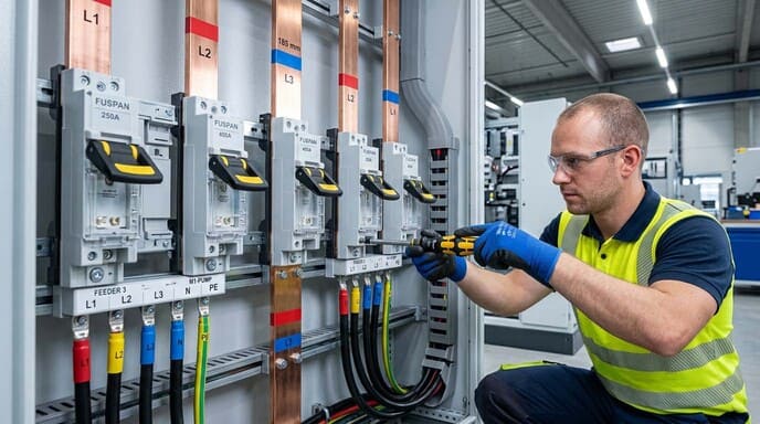
Assembling an MCB panel involves mounting the enclosure, installing DIN rails, securing the main incoming supply, connecting the busbar system, mounting individual MCBs, wiring neutral/earth connections, terminating outgoing circuits, and conducting thorough testing. This process requires careful attention to manufacturer specifications, local electrical codes, proper torque settings, and systematic circuit identification.

The assembly process has evolved significantly with the introduction of modular components and integrated busbar systems that dramatically reduce installation time while improving reliability.
Modern Assembly Methods and Efficiency Improvements
In my role supporting electrical contractors and panel builders, I've witnessed firsthand how modern assembly techniques have transformed the efficiency and reliability of MCB panel installations.
Traditional assembly methods involved time-consuming wire-by-wire connections from the main incomer to each MCB. This approach created panels with excessive wiring, increased potential for connection failures, and limited flexibility for modifications. Today's advanced assembly systems use integrated busbar solutions that dramatically reduce both assembly time and failure points.
For example, I recently worked with a panel shop that was building distribution boards for a large commercial development. By switching from traditional wiring to our modular busbar system7, they reduced assembly time per panel from approximately 4 hours to just 75 minutes – an efficiency improvement of nearly 70%. More importantly, they eliminated dozens of potential failure points by replacing individual wires with a single continuous busbar.
The modern assembly process typically follows these steps, with key considerations at each stage:
| Assembly Stage | Traditional Method | Modern Approach | Key Benefits |
|---|---|---|---|
| Enclosure Preparation | Basic mounting of backplate | Pre-engineered layouts with mounting templates | Consistent spacing, optimized layout |
| Power Distribution | Individual wires from incomer to each MCB | Integrated busbar systems with insulated connectors | Reduced labor, fewer failure points, better heat dissipation |
| MCB Mounting | Individual securing and wiring of each device | Clip-on connection to pre-installed busbar system | Faster installation, consistent connections |
| Circuit Identification | Manual application of wire markers and labels | Pre-printed identification systems with standardized labeling | Improved clarity, consistency across installations |
| Testing and Verification | Point-to-point continuity testing of all connections | Simplified verification of main busbar connections | Faster commissioning, more thorough testing |
One particularly innovative approach I've helped clients implement is the use of "plug and play" busbar systems that allow MCBs to connect directly to the power distribution system without individual wires. This not only speeds initial assembly but makes future modifications much simpler – MCBs can be added, removed, or replaced without disrupting adjacent circuits.
The most efficient panel shops I work with have embraced these modern assembly methods8 and developed standardized workflows that ensure consistency across all their builds. This systematic approach not only improves productivity but also enhances quality control by reducing variation between assemblies.
What is the Difference Between MCB and Normal Breaker?
During client consultations, I'm often asked about the distinctions between different circuit protection devices. Understanding these differences helps in selecting the right protection for specific applications.
MCBs (Miniature Circuit Breakers) differ from "normal" breakers (typically referring to MCCBs or Molded Case Circuit Breakers) primarily in size, current capacity, and breaking capacity. MCBs handle currents up to 100A with breaking capacities typically between 6-10kA, while MCCBs manage currents up to 1600A with breaking capacities up to 100kA. MCBs use standardized DIN rail mounting, while MCCBs usually require panel mounting.

These differences impact not just the selection of individual protection devices but the entire approach to designing distribution systems.
Comparative Analysis for Application Selection
Through my work with diverse electrical projects, I've developed a practical understanding of when each breaker type is most appropriate. This knowledge helps clients avoid both under-protection (creating safety risks) and over-specification (unnecessarily increasing costs).
Last year, I consulted on a factory expansion project where the electrical contractor initially specified MCCBs throughout the secondary distribution system. After reviewing their actual load requirements and fault level calculations, we determined that MCBs would provide adequate protection for most circuits while offering substantial cost savings. We ultimately designed a hybrid system9 using MCCBs for main distribution and MCBs for sub-distribution, optimizing both protection and budget.
The key differences that drive application selection include:
| Characteristic | MCB (Miniature Circuit Breaker10) | MCCB (Molded Case Circuit Breaker11) | Selection Implications |
|---|---|---|---|
| Current Rating | Typically 0.5A to 100A | Typically 16A to 1600A | MCBs for branch circuits, MCCBs for feeders and mains |
| Breaking Capacity | 6kA to 10kA (some up to 25kA) | 16kA to 100kA | MCCBs for higher fault current environments |
| Size/Footprint | Compact, standardized widths | Larger, varies by manufacturer | MCBs where space is limited or standardization important |
| Mounting Method | DIN rail mounting | Panel mounting with bolts | MCBs for modular systems with frequent changes |
| Adjustability | Fixed settings | Often adjustable trip settings | MCCBs where fine-tuning protection is needed |
| Trip Units | Non-interchangeable thermal-magnetic | Often interchangeable (thermal-magnetic, electronic) | MCCBs for sophisticated protection schemes |
| Accessories | Limited options | Extensive (aux contacts, shunt trips, motor operators) | MCCBs for complex control requirements |
| Standards | IEC/EN 60898 | IEC/EN 60947 | Different testing regimes and applications |
In practical applications, these differences translate into distinct usage patterns. MCBs excel in final distribution applications where space is limited, standardization is valuable, and protection requirements are relatively straightforward. MCCBs are better suited for power distribution closer to the source, where fault currents are higher, adjustability is beneficial, and more sophisticated protection schemes may be required.
I've found that many smaller commercial and industrial facilities benefit from an integrated approach that uses MCCBs for incoming supply and main distribution, with MCBs handling the sub-distribution to individual circuits. This creates a protection hierarchy that provides appropriate protection at each level while optimizing cost and space requirements.
Conclusion
MCB panel assemblies represent the evolution of electrical distribution systems, offering standardized, efficient solutions for circuit protection. The integration of quality components, thoughtful design, and modern assembly methods creates systems that are faster to install, more reliable in operation, and easier to maintain than traditional alternatives.
-
Explore this link to understand how a well-designed MCB panel assembly can enhance efficiency and reliability in electrical systems. ↩
-
Discover the advantages of modular MCB panel assemblies and how they can streamline your electrical installations. ↩
-
Learn about best practices in busbar design to ensure safety and efficiency in your electrical panel systems. ↩
-
Discover the workings of the dual-protection mechanism in MCBs to improve your understanding of circuit protection and design. ↩
-
Learn about trip curve classifications to tailor MCB protection to your specific needs, ensuring optimal performance in electrical systems. ↩
-
Explore this link to understand the various MCB types and their specific applications, enhancing your knowledge for better circuit protection strategies. ↩
-
Explore how modular busbar systems can enhance efficiency and reliability in electrical panel assembly, transforming your workflow. ↩
-
Learn about modern assembly methods that boost efficiency and reliability in electrical panel building, ensuring high-quality results. ↩
-
Discover the concept of hybrid systems in electrical distribution for optimized protection and cost efficiency. ↩
-
Explore the benefits of Miniature Circuit Breakers to understand their role in efficient electrical protection and cost savings. ↩
-
Learn about Molded Case Circuit Breakers to see how they can enhance safety and performance in high-load environments. ↩