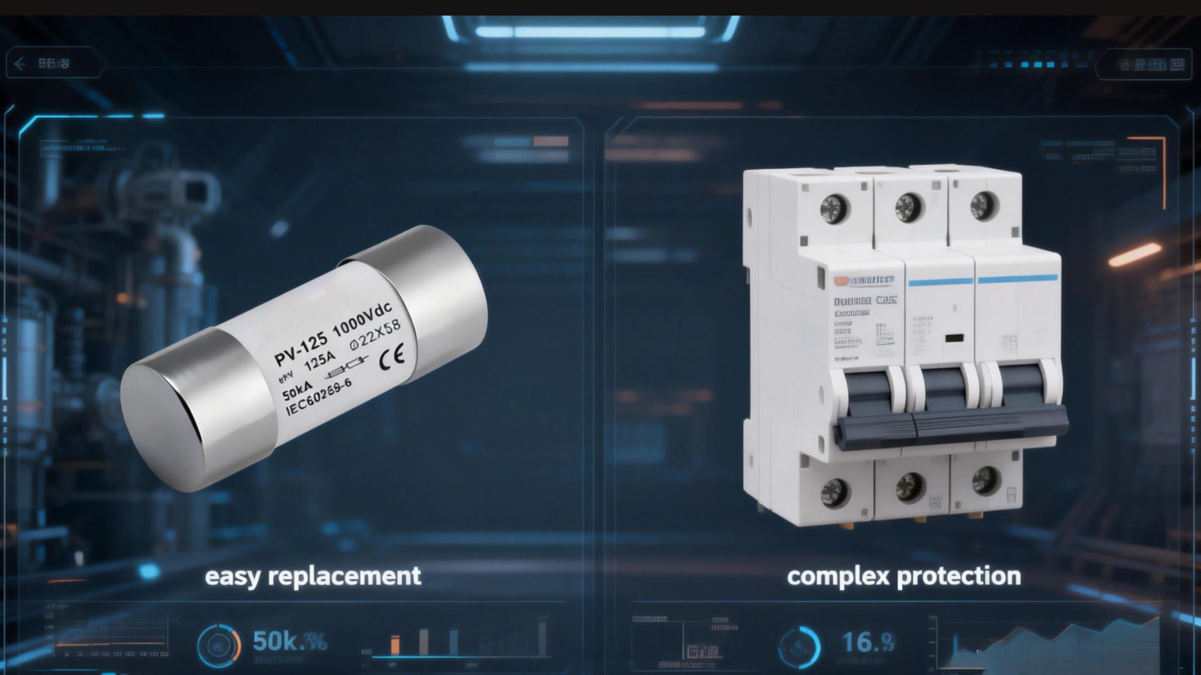
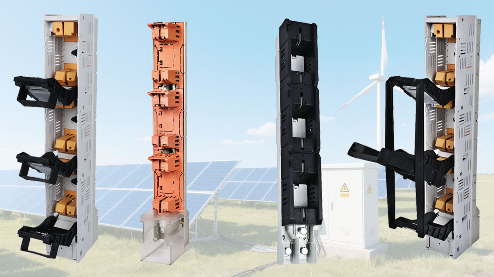
Selecting the wrong DC breaker for your solar system creates serious safety hazards. Many installers apply AC breaker logic to DC systems, resulting in dangerous arc flash risks, equipment damage, and protection failures during critical fault events.
To choose the right DC breaker1 for a PV system, you must select one rated for DC applications with appropriate voltage rating2 (≥1.25× system maximum voltage), current rating3 (≥1.25× maximum circuit current), and sufficient interruption capacity4 to handle the maximum potential fault current5.
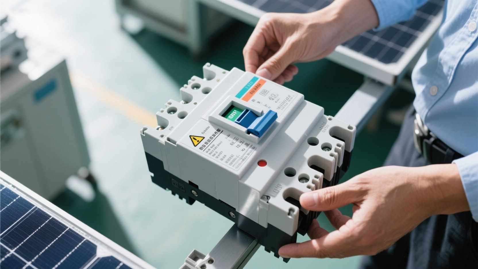
After specifying components for hundreds of solar installations, I've seen how proper DC breaker selection makes the difference between a safe, reliable system and a dangerous liability. Many designers focus solely on current ratings while overlooking critical DC-specific requirements. Let me share what I've learned to help you make better protection choices.
How to Size a DC Breaker for Solar?
Many installers simply pick a breaker that matches their wire ampacity. This dangerous approach ignores critical factors like voltage derating and temperature compensation that can cause protection failures when you need them most.
To size a DC breaker for solar, multiply the panel's short-circuit current6 (Isc) by 1.25 for ambient conditions, then by another 1.25 for continuous operation (total 1.56× Isc). Ensure the breaker has sufficient DC voltage rating for your maximum system voltage including temperature adjustments.
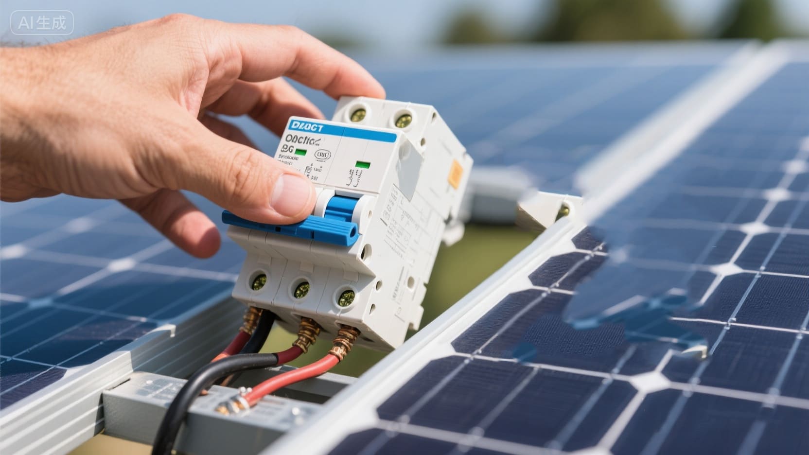
When sizing DC breakers for solar applications, you need to consider several interconnected factors to ensure proper protection without nuisance tripping7. This process requires a methodical approach.
DC Breaker Sizing Factors for Solar Applications
| Factor | Formula | Example Calculation | Notes |
|---|---|---|---|
| String Current | Isc from panel datasheet | 9.8A per string | Base value from manufacturer |
| Environmental Correction | Isc × 1.25 | 9.8A × 1.25 = 12.25A | Accounts for irradiance variations |
| Continuous Load Factor | Result × 1.25 | 12.25A × 1.25 = 15.31A | NEC requirement for continuous loads |
| Temperature Derating | Check manufacturer derating tables | 15.31A ÷ 0.8 = 19.14A | For installations in high temp environments |
| Minimum Breaker Size | Round up to next standard size | 20A DC breaker | Standard breaker sizing |
From my experience, one of the most overlooked aspects of breaker sizing is the impact of temperature on both current-carrying capacity and voltage ratings. Solar equipment regularly operates at elevated temperatures, especially in rooftop installations where ambient temperatures can exceed 70°C. At these temperatures, standard breaker performance curves shift significantly.
I always recommend calculating your maximum system voltage using the lowest expected site temperature, then applying a 1.25 multiplier to determine minimum breaker voltage rating. For example, a 600V nominal system might reach 720V in cold conditions, requiring a breaker rated for at least 900V DC. Using a breaker with inadequate voltage rating creates an arc extinction8 risk during fault conditions - something I've unfortunately witnessed firsthand when called to investigate system failures.
For multi-string systems, it's tempting to simply add string currents when sizing combining breakers9, but this approach fails to account for the uneven current distribution that often occurs in real-world conditions. I typically recommend adding an additional 10% margin for combining applications to accommodate these imbalances.
How Do I Know What Size DC Breaker I Need?
Undersized breakers trip constantly while oversized ones fail to provide protection. This common problem happens because installers don't account for all the variables affecting real-world circuit performance10 in solar applications.
The right size DC breaker for your solar system must have a current rating at least 1.56 times the short-circuit current (Isc) of your array, a voltage rating exceeding your maximum system voltage by 25%, and an interruption capacity suitable for the maximum potential fault current.
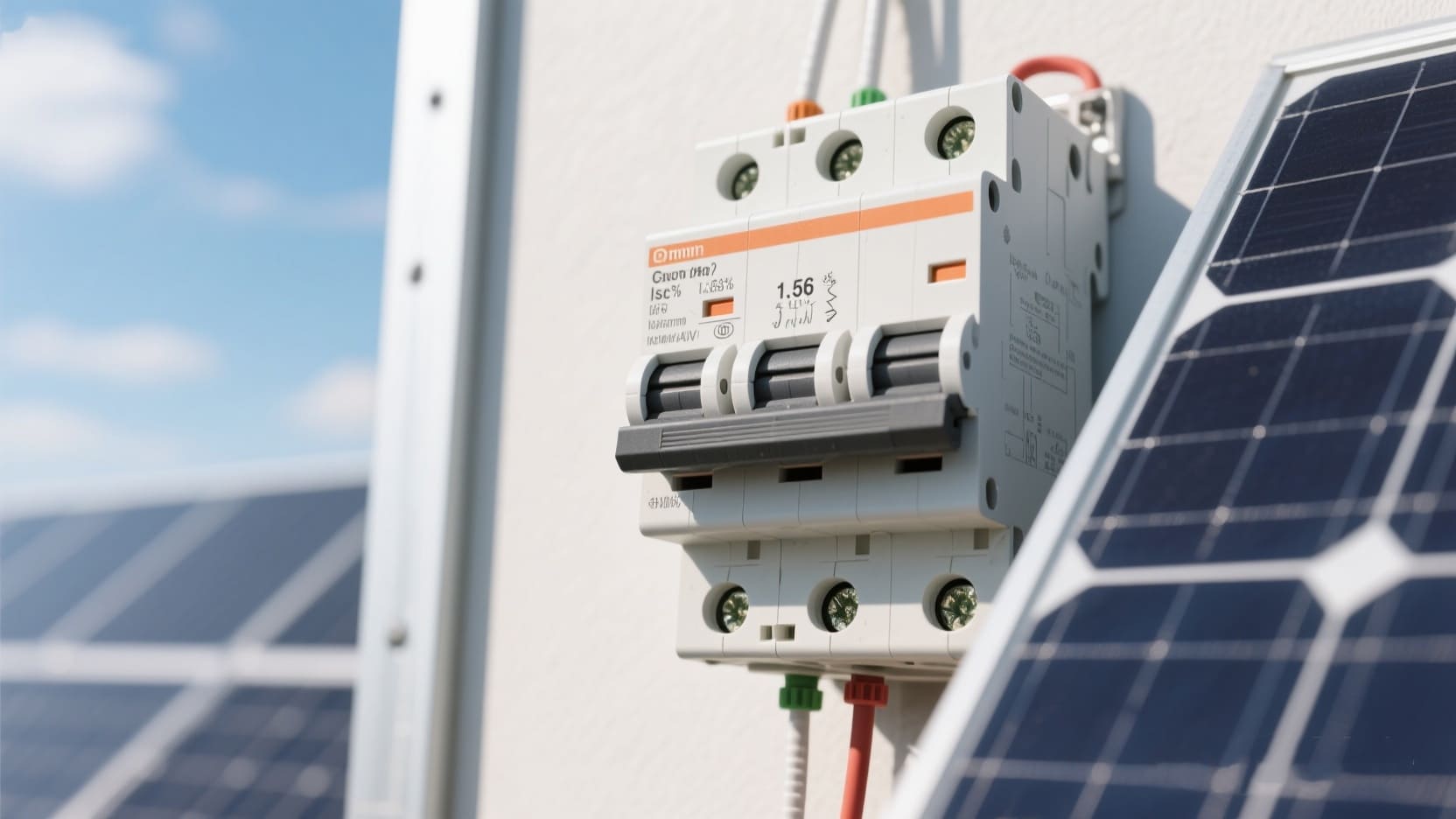
Determining the proper DC breaker size requires careful analysis of both the system parameters and environmental conditions11 that will affect breaker performance.
DC Breaker Selection Matrix by System Type
| System Voltage | Application | Recommended Voltage Rating | Interruption Capacity | Special Requirements |
|---|---|---|---|---|
| 12-48V Battery | Off-grid/Battery | 125-250V DC | Min. 5kA | High magnetic trip setting |
| 100V String | String protection | 250V DC | Min. 5kA | Time-delay feature |
| 600V String | Commercial string | 1000V DC | Min. 10kA | Voltage de-rating at altitude |
| 1000V+ Systems | Utility scale | 1500V DC | 20kA+ | Remote operation capability |
When determining DC breaker size, I always begin by understanding the worst-case scenarios. For battery-connected systems12, the fault current can be massive – often exceeding 10,000 amps in larger systems – requiring breakers with high interruption capacity. Conversely, PV string circuits are current-limited by the panels themselves, but present challenges in terms of sustained arc extinction due to their high voltages.
Altitude is another factor that significantly impacts DC breaker selection. Systems installed at elevations above 2,000 meters require voltage de-rating13 due to the reduced air density affecting arc extinction capabilities. For every 100 meters above 2,000, I recommend reducing the breaker's voltage rating by approximately 0.5%. This means a breaker rated for 1000V DC at sea level might only be suitable for 950V DC operation at 3,000 meters elevation.
Another critical consideration is the difference between breaking capacity and operational current. Many installers select breakers based solely on their continuous current rating, overlooking the maximum fault current the breaker can safely interrupt. For battery-connected solar systems, I recommend breakers with interruption ratings at least three times the maximum possible fault current to ensure safe operation throughout the system's lifetime.
How to Select a DC Circuit Breaker?
Many solar designers mistakenly treat DC breakers like their AC counterparts. This fundamental error ignores the unique arc extinction challenges of DC current, leading to catastrophic breaker failures during fault events.
To select a DC circuit breaker for solar applications, choose one specifically rated for DC use with appropriate voltage rating, current capacity, and interruption rating. Consider environmental conditions, mounting options, and coordination with other system protection devices14.
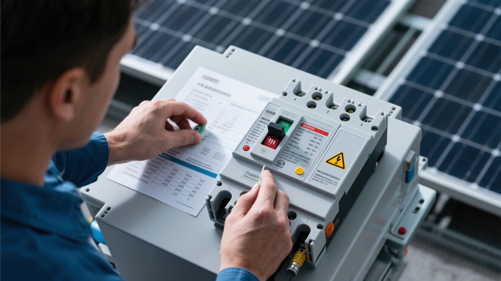
The process of selecting the right DC circuit breaker involves evaluating multiple technical parameters against your specific application requirements.
DC Circuit Breaker Selection Criteria
| Selection Criteria | Importance | Considerations | Impact of Poor Selection |
|---|---|---|---|
| DC Voltage Rating | Critical | Must exceed maximum system voltage by 25% | Arc flash hazard, breaker failure |
| Current Rating | High | Must handle 156% of Isc | Nuisance tripping, overheating |
| Interruption Capacity | Critical | Must exceed maximum fault current | Catastrophic failure during faults |
| Temperature Rating | Medium | Match installation environment | Premature aging, false trips |
| Terminal Type | Medium | Compatible with conductor size | Connection failures, hotspots |
| Trip Characteristic | Medium | Appropriate for circuit type | Nuisance tripping, poor coordination |
| Mounting Type | Low | Compatible with enclosure | Installation difficulties |
In my work with large-scale solar installations, I've found that breaker selection often requires balancing multiple competing factors. One of the most challenging aspects is proper coordination between different protection devices in the system. A properly coordinated protection scheme ensures that the breaker closest to a fault operates first, minimizing the impact on the rest of the system.
For this coordination to work effectively, you need to select breakers with appropriate time-current characteristics that complement other protective devices like fuses and electronic protections in inverters. I typically recommend creating a coordination study for any system above 50kW to ensure proper selective operation of all protective devices.
Another often-overlooked aspect of DC breaker selection is the terminal capacity and type. DC connections tend to experience more thermal cycling15 than AC connections, making the quality of the termination critically important. I prefer breakers with copper terminals16 rated for at least 75°C and torque specifications appropriate for the conductor size. Aluminum terminals require special installation procedures including anti-oxidation compound and precise torquing to prevent connection failures.
For systems operating in harsh environments, I recommend breakers with additional environmental ratings. Standard breakers are typically rated for indoor, pollution degree 2 environments. For outdoor installations or areas with conductive pollution, specially rated breakers are necessary to ensure reliable operation throughout the system's life.
What is the 80% Rule for Circuit Breakers?
The misapplied 80% rule17 causes constant confusion in solar design. Installers often apply it incorrectly, either under-protecting circuits or needlessly oversizing equipment, wasting thousands in unnecessary materials.
The 80% rule stipulates that circuit breakers shouldn't be loaded beyond 80% of their rating for continuous loads (operating 3+ hours). For solar systems, which are continuous by definition, this means breakers must be sized at least 125% of the maximum continuous current.
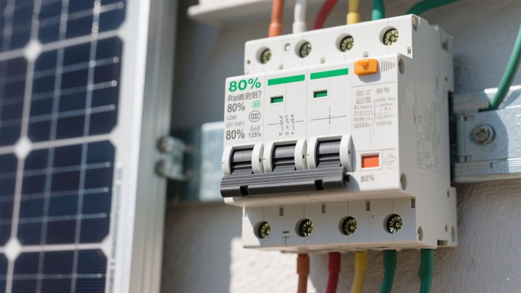
The 80% rule has specific applications in electrical systems and is particularly relevant for solar installations due to their continuous operation nature.
80% Rule Application in Different Scenarios
| Application | Standard Load | Continuous Load | Example Calculation | Notes |
|---|---|---|---|---|
| Residential Circuit | 100% of breaker rating | 80% of breaker rating | 20A breaker = 16A continuous | Standard NEC application |
| Solar Source Circuit | Not applicable | 80% of breaker rating | 15A continuous needs 20A breaker | PV always continuous |
| Inverter Output | Not applicable | 80% of breaker rating | 40A output needs 50A breaker | Inverted AC is continuous |
| Battery Circuit | Case-specific | 80% of breaker rating | 100A discharge needs 125A breaker | Depends on discharge profile |
The origin of the 80% rule stems from the thermal characteristics of circuit breakers. When current flows through a breaker, it generates heat. For momentary loads, this heat dissipates before causing issues. However, continuous loads create sustained heating that can affect breaker performance and longevity.
In my experience designing large commercial solar systems, I've found that the 80% rule must be applied at multiple points in the system. For example, both the DC input circuits to the inverter and the AC output circuits must follow this rule since both carry continuous currents. However, the application differs slightly based on the specific equipment and code requirements.
What often confuses installers is how this rule interacts with the other NEC factors for solar. The code requires applying a 1.25 factor to account for environmental conditions (125% of Isc), and then the 80% rule effectively adds another 1.25 factor (or requires a breaker rated at 125% of the calculated current). This compounded calculation results in breakers sized at approximately 156% of the panel's rated short-circuit current.
For battery-based systems, the application becomes even more complex. Battery charging circuits are typically continuous, requiring the 80% rule application. However, discharge circuits may or may not be continuous depending on the application. For backup power systems with occasional use, standard breaker ratings might be appropriate. For daily cycling systems or off-grid applications, I recommend treating all battery circuits as continuous and applying the 80% rule consistently.
Conclusion
Selecting the right DC breaker for your PV system demands attention to voltage ratings, temperature considerations, and proper coordination with other protection devices. Following these guidelines ensures your solar installation remains safe and reliable throughout its operational life.
-
Understanding DC breakers is crucial for ensuring safety and reliability in solar installations. ↩
-
Learn how to accurately determine voltage ratings to prevent equipment failure in solar applications. ↩
-
Understanding current ratings helps ensure that your DC breaker can handle the system's demands. ↩
-
Discover why interruption capacity is critical for safety during fault conditions in solar systems. ↩
-
Understanding fault current is vital for ensuring your DC breaker can handle potential overloads. ↩
-
Calculating short-circuit current is essential for selecting the right DC breaker for your solar system. ↩
-
Understanding nuisance tripping can help you avoid frequent breaker failures in your solar installation. ↩
-
Explore the challenges of arc extinction in DC circuits to ensure safe operation of your solar system. ↩
-
Learn the best practices for sizing combining breakers to ensure balanced current distribution. ↩
-
Analyzing circuit performance helps ensure that your DC breaker selection meets all operational needs. ↩
-
Explore how different environmental factors impact the performance and selection of DC breakers. ↩
-
Learn about the specific requirements for breakers in battery-connected systems to ensure safety. ↩
-
Understanding voltage de-rating is crucial for selecting breakers in high-altitude solar installations. ↩
-
Explore various protection devices to understand how they work together with DC breakers. ↩
-
Learn how thermal cycling impacts breaker performance to ensure reliable connections in your system. ↩
-
Discover the advantages of using copper terminals for better performance and reliability in DC circuits. ↩
-
Understanding the 80% rule is essential for proper sizing of breakers in continuous load applications. ↩

