Confused about power distribution terms? Specifying components like busbars versus busways requires clear understanding to avoid costly errors in large projects. Let's clarify the key differences.
A busbar is the conductive metal strip (usually copper or aluminum) inside electrical equipment like panels or switchgear. A busway (or bus duct) is a prefabricated, enclosed assembly containing busbars, used to distribute power between different locations or pieces of equipment.
Understanding this distinction is crucial. One is a component, the other is a system. Knowing which one fits the application helps procurement managers like Mr. Abdu source the right solutions for efficient and safe power distribution in industrial or new energy projects. Let's explore further.
Are bus and busbar the same?
Heard people just say "bus" in electrical contexts? This common shortcut can sometimes lead to confusion when discussing specific components. Is it just short for busbar, or something else?
Often, "bus" is simply shorthand for "busbar," referring to the conductor bar itself. However, context matters, as "bus" can broadly mean any common point of electrical connection, which might include the entire assembly.
Let's break this down. The term "bus" in electrical engineering originates from "omnibus bar," meaning a bar common to many connections. Over time, it got shortened.
Defining the Terms
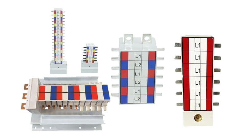
- Busbar: This specifically refers to the physical conductor – the rigid metal strip or bar (like the ones we manufacture at Fuspan) designed to carry significant current within equipment. Think of it as the primary component.
- Bus (Shorthand): When someone says "connect it to the bus," they usually mean "connect it to the busbar1." It's informal but very common.
- Electrical Bus2 (Concept): In a broader sense, an electrical bus is a node or junction where multiple circuits connect. A busbar creates this common connection point physically. Sometimes, a whole system like a busway might be informally referred to as "the bus."
Clarifying the Usage
It's important to understand the context. When discussing internal panel components, "bus" almost always means "busbar." When talking about power distribution between buildings or large equipment sections, "bus" might refer to a busway system3.
| Term | Primary Meaning | Typical Context | Fuspan's Focus |
|---|---|---|---|
| Busbar | The physical conductor bar | Inside panels, switchgear, assemblies | Manufacturing high-quality busbars and components |
| Bus | Shorthand for busbar; common connection | Informal technical discussions, schematics | The component referred to by the shorthand |
| Busway/Duct | Enclosed distribution system | Power transmission between locations | Supplying components used within connected gear |
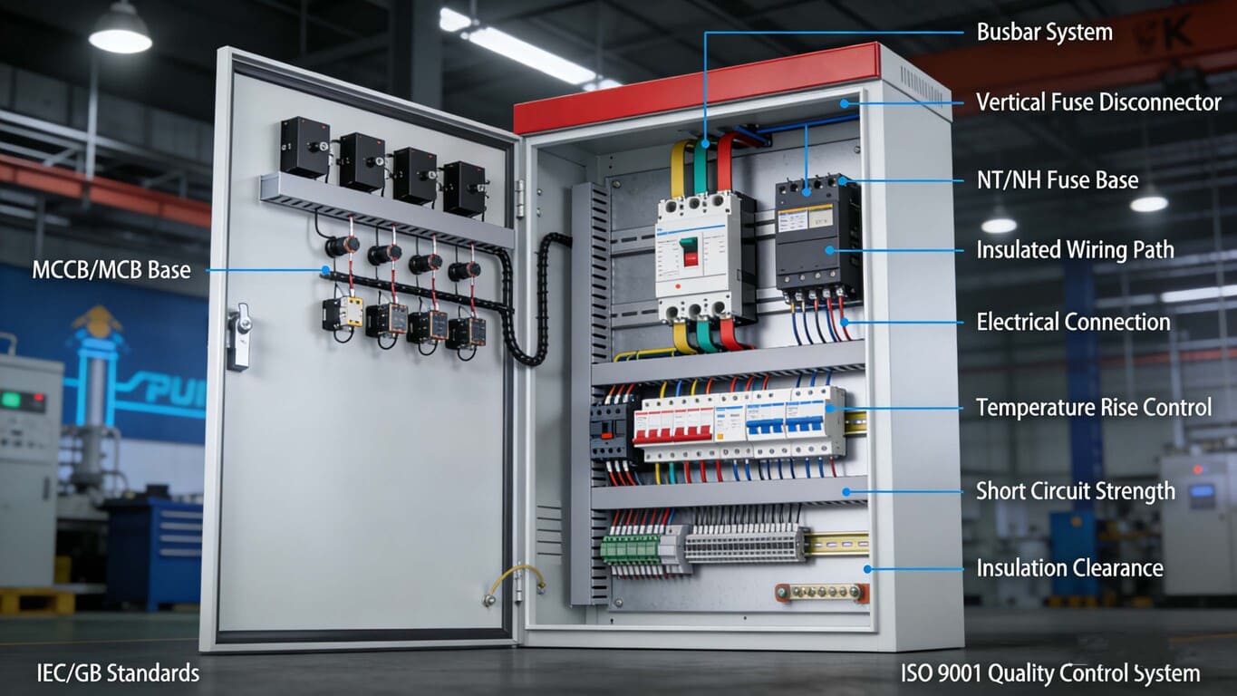
For someone like Mr. Abdu needing precise components meeting IEC standards, using the term "busbar" is clearer when specifying the actual conductor needed within panels or assemblies we provide, like our MCB/MCCB pan assemblies. Using "bus" informally is fine in discussion, but "busbar" is better for specifications.
What is the difference between a busbar and a bus duct?
Choosing how to route high currents? Deciding between running bare conductors inside a panel versus using a self-contained trunking system requires understanding these distinct approaches. What's the difference?
A busbar is the bare or insulated conductor bar used inside enclosures like switchgear. A bus duct (or busway) is a complete, factory-assembled enclosed system containing busbars, designed for distributing power between equipment or locations.
!
Think of it like this: busbars are the highways inside a city (panel), while bus ducts are the protected inter-city highways connecting different points. As my insight noted, bus ducts offer advantages in specific scenarios.
Key Differences Explored
- Form:
- Busbar: A component, a strip or bar of conductive metal, sometimes coated but often installed bare within an enclosure, relying on spacing and insulators for safety. Installation4 can be intricate, requiring careful alignment and connection.
- Bus Duct/Busway5: A system. It includes busbars pre-installed within a protective metal or (less commonly) heavy-duty plastic enclosure, complete with insulators and often designed for modular connection.
- Application:
- Busbar: Used within switchboards, panelboards, motor control centers for internal power distribution to breakers, fuses, etc.
- Bus Duct/Busway: Used to transmit power between major electrical components (e.g., transformer to main switchboard), along factory floors, or vertically in buildings.
- Installation:
- Busbar: Requires careful on-site mounting, insulation, and connection within the panel. Can be labor-intensive and requires skill to ensure safety clearances. Lines can become messy if not well planned.
- Bus Duct/Busway: Modular sections are simply bolted together. Installation is generally faster and simpler than running multiple large cables, especially over distance. Safety is inherent due to the enclosure.
- Protection & Safety:
- Busbar: Relies on the main equipment enclosure and internal clearances/barriers for protection against contact and environment.
- Bus Duct/Busway: Fully enclosed (often IP rated), providing mechanical protection and enhanced safety against accidental contact. The enclosure is typically grounded. Offers a long service life due to protection.
| Feature | Busbar | Bus Duct / Busway | Relevance to Mr. Abdu's Needs |
|---|---|---|---|
| Nature | Component | System | Specifies components vs. distribution systems |
| Location | Inside equipment | Between equipment/locations | Panel internals vs. facility power routing |
| Enclosure | Relies on panel/switchgear enclosure | Self-contained enclosure | Component specification vs. system specification |
| Installation | Detailed, within panel build | Modular assembly, simpler routing | Fuspan provides components; others provide systems |
| Safety | Depends on panel design & installation | Enhanced by enclosure, factory-built | Need for reliable components within safe systems |
At Fuspan, we excel at manufacturing the high-quality busbars and integrated assemblies (like pan assemblies) that go inside the electrical panels. While we don't make the large bus duct systems themselves, our components are essential parts of the switchgear that these systems connect to, ensuring reliability right where the power is distributed and protected.
What is the purpose of a busway?
Need to move a lot of power across your facility efficiently? Running numerous large, heavy cables can be costly, time-consuming, and take up significant space. Busways offer a streamlined alternative.
The main purpose of a busway (or bus duct) is to efficiently and safely transport large amounts of electrical power over distances, typically between major electrical equipment or along distribution routes, using a compact, pre-engineered, enclosed system.

Imagine needing to get power from the main transformer to switchgear located 50 meters away, or distributing power down a long assembly line. This is where busways shine. They replace multiple parallel cable runs with a single, integrated solution.
Advantages and Applications
Busways provide several key benefits, especially relevant for the large industrial or new energy projects Mr. Abdu manages:
- High Current Capacity6: Designed to handle substantial currents efficiently, often more effectively than equivalent cable setups due to better heat dissipation within the engineered structure.
- Lower Voltage Drop7: Over longer distances, busways often exhibit lower voltage drop compared to cables carrying the same power, improving energy efficiency.
- Space Savings: A single busway trunking is typically more compact than multiple large cable trays.
- Faster Installation: Modular sections bolt together quickly. Installing tap-off units for local power drops is simpler than cutting and splicing large cables. This addresses the need for short project lead times.
- Flexibility & Scalability8: Easy to add or relocate tap-off points as facility needs change. The system can be extended or modified more readily than embedded conduit and cable.
- Enhanced Safety: The live conductors are fully enclosed within a grounded metal housing, significantly reducing the risk of accidental contact compared to open wiring or even cable trays. Reliability is high due to factory-controlled manufacturing.
Typical Use Cases:
- Connecting utility transformers to main building switchgear.
- Feeding power to large Motor Control Centers (MCCs).
- Distributing power along manufacturing or assembly lines.
- Vertical power distribution (risers) in high-rise buildings.
- Power distribution in data centers.
While Fuspan focuses on the critical components within the switchgear (like busbars, fuse disconnectors, pan assemblies), understanding busways is important as our equipment often forms the start or end point of these distribution systems. Ensuring our components meet IEC standards and offer high reliability is vital for the overall performance of the power network connected by busways.What is the difference between a bus coupler and a busbar?
Designing complex switchgear with multiple power sources or sections? You need ways to connect these sections reliably and safely. This involves more than just the power conductors themselves.
A busbar is the physical conductor carrying the electrical current. A bus coupler is a switching device (like a circuit breaker or isolator) specifically used to connect or disconnect two separate busbars or sections of a busbar system within switchgear.

Think of busbars as the parallel roads carrying traffic (current). A bus coupler acts like a controllable bridge or junction connecting these roads, allowing traffic to flow between them or isolating them when needed. It's an active component, unlike the passive busbar.Function and Purpose
The role of a bus coupler9 is crucial for enhancing the reliability, flexibility, and maintainability of electrical distribution systems, especially in large facilities:
- Connecting Sources: Allows connecting two independent power sources (e.g., two transformers, or mains and generator) to feed the switchgear10, often ensuring only one is connected at a time or allowing parallel operation.
- Sectionalizing: Divides a long switchboard busbar into sections. This allows part of the switchboard to be de-energized for maintenance while the rest remains operational. It also helps contain faults to one section.
- Load Balancing/Transfer: Enables shifting loads between different bus sections or power sources as needed.
Key Differences Summarized
Feature Busbar Bus Coupler Relevance to Mr. Abdu's Needs Function Conducts current Switches/Connects/Isolates bus sections Needs reliable conductors AND reliable switching Type Passive component (conductor) Active component (switching device) Component specification vs. system operation strategy Location Forms the main power path within sections Located between busbar sections or sources Integral part of switchgear design & reliability Complexity Simple metallic bar Complex mechanism (breaker, isolator, controls) Basic component vs. engineered device While Fuspan manufactures the core busbars and related components like fuse switch disconnectors (which can act as simple isolating points), dedicated bus couplers are typically larger circuit breakers or switches specifically rated and designed for this interconnection task. Understanding the role of bus couplers is vital for Mr. Abdu when specifying switchgear for large projects, as the configuration directly impacts power availability and maintenance strategies. Reliable busbars from Fuspan are essential foundations upon which these complex, reliable switchgear systems are built.
Conclusion
Busbars are conductors inside equipment; busways are enclosed systems distributing power between locations. Bus couplers are switches connecting bus sections. Understanding these distinctions ensures correct specification for reliable power systems.
-
Understanding busbars is crucial for anyone involved in electrical engineering, as they are key components in power distribution systems. ↩
-
Exploring the concept of an electrical bus can enhance your knowledge of circuit connections and power distribution systems. ↩
-
Learning about busway systems can provide insights into efficient power transmission solutions for large installations. ↩
-
Learning about installation differences can help in choosing the right system for specific electrical needs and safety requirements. ↩
-
Exploring bus duct systems can reveal their benefits in efficiency and safety for large-scale electrical installations. ↩
-
Explore how High Current Capacity in busways enhances efficiency and performance in industrial applications. ↩
-
Learn how Lower Voltage Drop in busways can lead to significant energy savings and improved system performance. ↩
-
Discover how Flexibility & Scalability in busway systems can adapt to changing facility needs, enhancing operational efficiency. ↩
-
Understanding bus couplers is essential for ensuring reliable and efficient electrical distribution in large facilities. ↩
-
Learning about switchgear components is crucial for designing efficient electrical systems and ensuring operational reliability. ↩