Confused about different electrical panel types? Busbar panels offer a structured, high-capacity way to manage power, but understanding them is key to reliable systems.
A busbar panel is an electrical enclosure that uses rigid conductive bars (busbars) instead of flexible wires to distribute power from a main source to multiple outgoing circuits efficiently and safely.
My insights show that busbar panels are fundamental, the absolute backbone for power flow in critical places like data centers and factories. They look simple, but their design and quality are vital. Let's explore what makes them different and so important.
What is the purpose of a busbar?
Tangled in complex high-current wiring? Busbars streamline power distribution, making panels cleaner, safer, and easier to manage for demanding electrical loads.
The purpose of a busbar is to consolidate and distribute electrical power efficiently within a panel, providing a robust, low-impedance path for high currents and simplifying connections to multiple circuits.
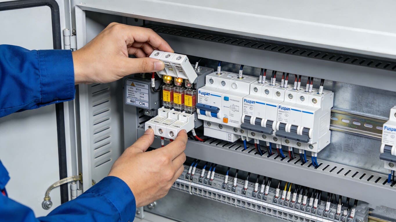
From my experience at Fuspan, the purpose goes way beyond just carrying electricity. It's about creating order and reliability. Think about assembling a large industrial control cabinet or a power distribution unit for a new energy project, like those Mr. Abdu handles. Using individual cables for every high-current connection quickly becomes a complex, space-consuming mess. Busbars provide a structured solution. They allow for a much higher power density in a smaller space compared to cables. This simplifies the panel layout significantly, making assembly faster and reducing potential wiring errors. Furthermore, a well-designed busbar system, like our integrated fuse switch disconnector setups or MCB/MCCB pan assemblies, makes future modifications or additions much easier than reworking bundled cables. It brings scalability and structure.
Deeper Dive into Purpose:
Let's break down the key reasons busbars are used:
- Consolidation: Acts as a central junction point, bringing power from one large source and making it available to many smaller circuits without numerous splices or distribution blocks.
- High Current Capacity1: Engineered to handle large currents efficiently with less voltage drop and better heat dissipation than equivalent cables, especially when bundled.
- Space Saving: Rigid structure allows for compact designs and organized component placement within the panel.
- Simplified Wiring: Reduces the quantity and complexity of wiring, leading to faster assembly, less labor cost, and fewer potential connection errors.
- Enhanced Safety2: Can be designed with insulation and specific clearances (like our touch-proof systems) to reduce the risk of accidental contact or short circuits.
- Modularity & Scalability3: Systems are often modular, allowing easier expansion or changes to the panel configuration.
| Feature | Benefit Provided by Busbar | Importance for Project Owners (like Mr. Abdu) |
|---|---|---|
| Consolidation | Centralized power distribution point | Simplified panel design and assembly |
| High Current | Handles large loads efficiently | Meets demands of industrial/energy sectors |
| Space Saving | Allows compact panel construction | Optimizes space usage in installations |
| Simplified Wiring | Faster assembly, fewer errors, lower labor cost | Shortens project timelines, improves quality |
| Enhanced Safety | Reduces risks of shorts and shocks | Ensures personnel safety, system reliability |
| Modularity | Easier future expansion/modification | Flexible system design, future-proofing |
So, the purpose isn't just conduction; it's about bringing efficiency, safety, and structure to power distribution, especially where high currents and reliability are critical.
What happens if a busbar fails?
Worried about system downtime? A busbar failure isn't just a minor issue; it can trigger major shutdowns, damage equipment, and pose serious safety risks.
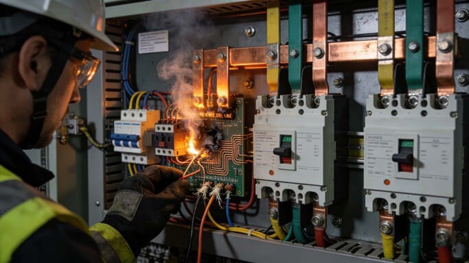
Busbar failure typically leads to immediate power interruption, potentially causing catastrophic equipment damage from short circuits or overheating, costly operational downtime, and severe safety hazards like arc flash or fire.
This is something I take very seriously based on my insights. We've seen firsthand how a seemingly small failure in a busbar connection can bring an entire operation to its knees. The financial impact of unexpected downtime, especially in manufacturing or critical infrastructure, can be enormous, far outweighing any perceived savings from using lower-quality components or skimping on installation procedures. Often, as I've noted, the failure isn't the bar itself breaking, but a connection point overheating due to improper torque, contamination, or vibration. This highlights why robust design, quality materials (meeting IEC standards), and meticulous assembly (like our ISO 9001 controlled process) are non-negotiable for reliability.
Deeper Dive into Failure Consequences:
Busbar failures generally fall into a few categories:
- Overheating/Meltdown4: Usually starts at connection points due to high resistance (loose bolts, corrosion, dirt) or overloading. This generates excessive heat, damaging insulation and potentially leading to open circuits or fires.
- Short Circuit/Arc Flash5: Caused by insulation failure, dropped tools, vermin, or incorrect phasing. The massive energy release can vaporize metal, create pressure waves, and cause severe burns or explosions. This is the most dangerous failure mode.
- Mechanical Failure6: Physical breakage or deformation due to vibration, impact, inadequate support, or thermal expansion/contraction stress. This leads to an open circuit or intermittent connection.
The results are consistently severe:- Total Power Loss: Circuits fed by the failed section go dead instantly.
- Cascading Damage: Short circuits can damage upstream breakers, transformers, and connected loads. Overheating can melt adjacent components.
- Extended Downtime: Repairing busbar systems, especially extensive damage, takes significant time and expertise.
- Safety Risks: Arc flash poses lethal danger. Fire can spread rapidly within enclosures.
- Financial Costs: Lost production, repair/replacement expenses, potential fines for safety incidents.
| Failure Mode | Primary Cause | Immediate Impact | Key Risk Factors |
|---|---|---|---|
| Overheating | Poor connection, overload, contamination | High temp, melting, potential fire, open circuit | Downtime, equipment damage, fire hazard |
| Short Circuit | Insulation breakdown, foreign object, phase error | Arc flash, explosion, immediate outage | Extreme safety hazard, severe damage |
| Mechanical Damage | Vibration, impact, poor support, thermal stress | Open circuit, intermittent power | Unreliable operation, eventual outage |
Ensuring busbar integrity through proper design, installation, and maintenance is critical to preventing these costly and dangerous outcomes. That’s why reliable connection integrity is a core focus for us at Fuspan.
What is a busbar panel?
Need to understand different panel types? A busbar panel uses solid bars for power distribution, offering a distinct advantage over traditional cable-wired panels in many situations.
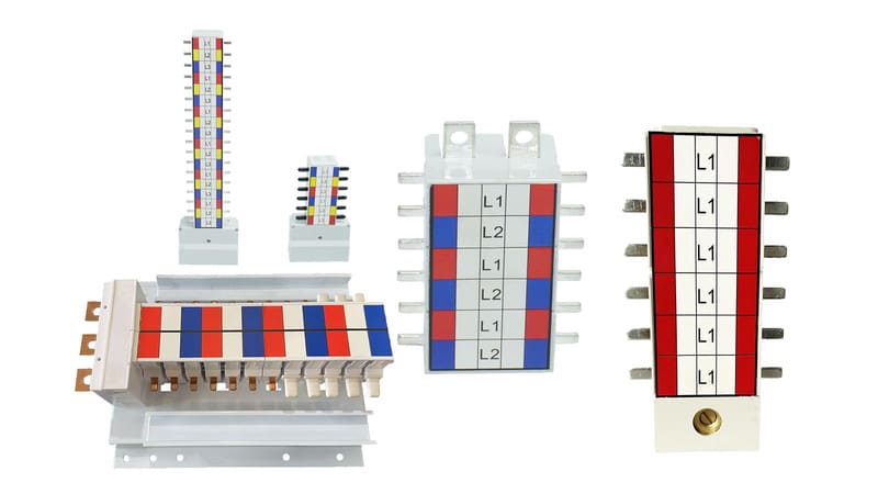
A busbar panel is an electrical switchgear or distribution board assembly where the main electrical conductors are rigid busbars, used to mount and interconnect protective devices like fuses or circuit breakers.

Think of it as the central nervous system for power in a building or industrial process. My insight is that these panels are the practical implementation of the busbar concept – moving from just the conductive bar to the entire integrated system. Instead of a tangled web of wires connecting the main incoming power to various circuit breakers or fuse switches, you have a clean, organized structure built around these busbars. This structure often includes the enclosure itself, the busbars mounted on insulators, the main incoming connection point, and provisions for easily mounting outgoing protective devices directly onto or connected to the busbars. Our Fuspan products, like vertical fuse switch disconnectors and MCB/MCCB pan assemblies, are designed to integrate seamlessly into such panels.
Deeper Dive into Busbar Panels:
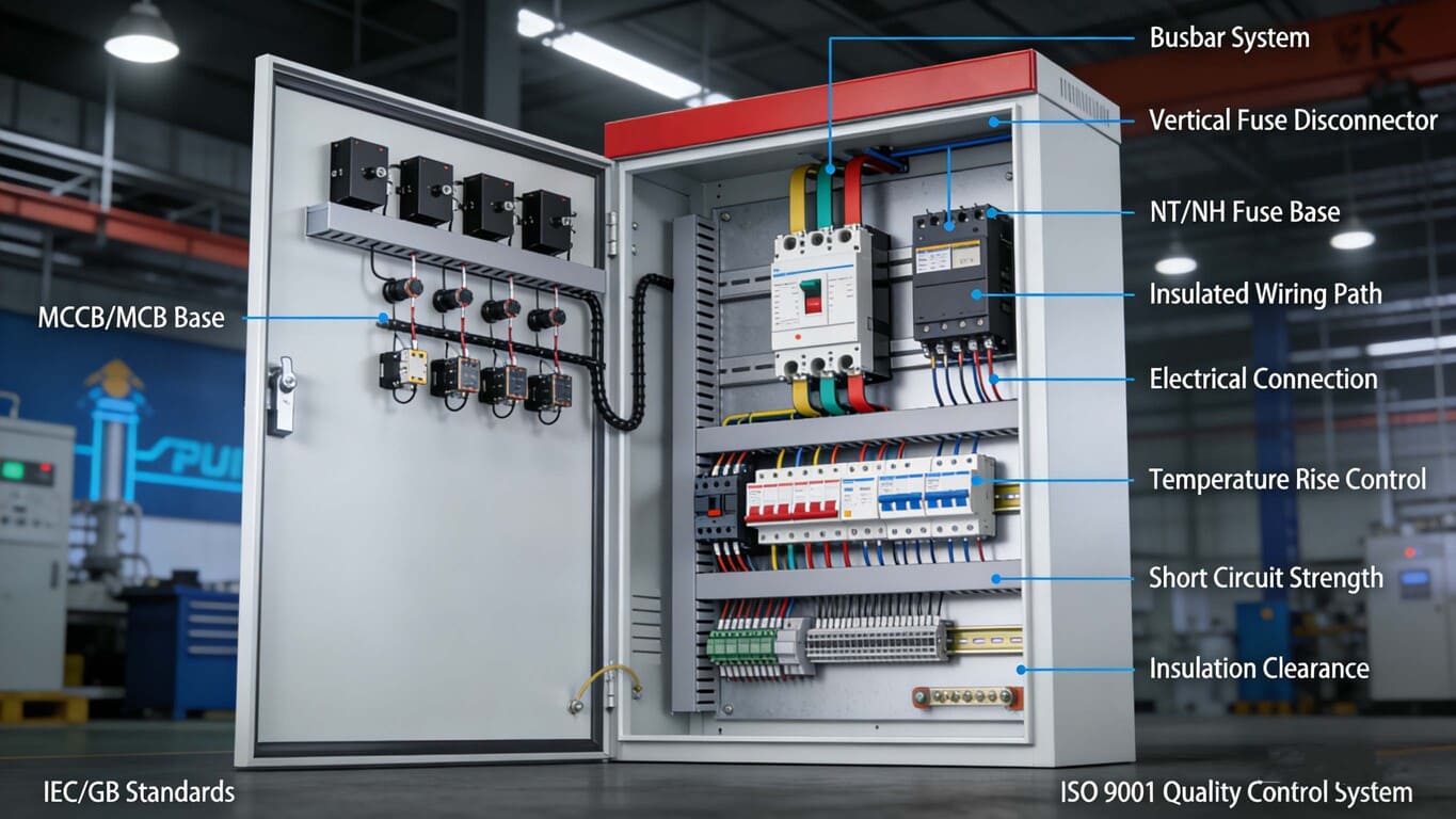
A busbar panel comprises several key elements working together:
- Enclosure: The cabinet housing all components, providing protection from the environment and personnel safety.
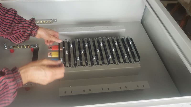
- Busbars: The core conductive elements (usually copper or aluminum bars) carrying the main current. These can be arranged for single-phase or three-phase power, plus neutral and ground.
- Insulators/Supports: Strong, non-conductive mounts that hold the busbars securely in place, maintaining required electrical clearances and preventing short circuits.
- Incoming Connection: Point where the main power feed connects to the busbar system (e.g., main lugs or a main circuit breaker/fuse switch).
- Outgoing Connections/Devices: Provisions for connecting outgoing circuits, often via circuit breakers, fuse holders (like our NT/NH range), or fuse switch disconnectors that mount directly to or tap off the busbars.
- Phase Barriers/Shrouding7: Insulation or barriers used to prevent accidental contact between phases or to ground, enhancing safety (a key feature we emphasize).
| Component | Function | Importance |
|---|---|---|
| Enclosure | Housing and protection | Safety, environmental protection |
| Busbars8 | Main power conduction and distribution | Efficiency, capacity, core of the system |
| Insulators/Supports9 | Secure mounting, electrical isolation | Safety, structural integrity, short prevention |
| Incoming Connection | Power entry point | Connects panel to the main supply |
| Outgoing Devices | Circuit protection and branching | Connects and protects individual loads |
| Barriers/Shrouding | Insulation, phase separation | Enhanced safety, prevents accidental contact |
Busbar panels offer a standardized, often type-tested solution for reliable power distribution, contrasting sharply with the custom, labor-intensive wiring of traditional panels, especially for higher power levels. They are essential for applications demanding consistency, safety, and efficiency.
How do I know if my bus bar is bad?
Concerned about potential busbar problems? Identifying a failing busbar early is crucial to prevent major outages and ensure safety in your electrical system.
Signs of a bad busbar include visible discoloration or melting near connections, unusually high temperatures (detected via thermal imaging), unexplained voltage drops, intermittent power issues, or evidence of corrosion.

Based on my insights, this is a critical question for maintenance teams. While catastrophic failure is often sudden (like a short circuit), degradation leading to failure, especially overheating at connections, can often be detected beforehand. Visual checks for discoloration, warping, or corrosion are the first step. But the real workhorse for predictive maintenance here is thermal imaging (thermography). Regularly scanning busbars and especially connection points under load can reveal hotspots – areas with higher resistance generating excess heat – long before they cause a meltdown. As I mentioned, the industry is looking towards more continuous monitoring, but thermal scans remain the most common proactive method.
Deeper Dive into Detecting Issues:
Identifying a failing busbar involves several methods, moving from basic checks to more advanced diagnostics:
- Visual Inspection: Look for obvious signs like:
- Discoloration/Charring: Indicates severe overheating has occurred, especially around bolts, joints, and terminations.
- Melting Insulation: Plastic components near the busbar showing heat damage.
- Corrosion: White, green, or rust-colored deposits on the busbar or connections, increasing resistance.
- Physical Damage: Cracks, bends, or loose connections.
- Thermal Imaging (Thermography)10: The most effective non-contact method. An infrared camera detects temperature differences. Hotspots, particularly at joints compared to the main bar, indicate high resistance and potential failure points. Regular scans under normal load conditions are key.
- Voltage Drop Measurement11: Measuring voltage along the busbar path under load. An excessive drop between points can indicate a poor connection or compromised section.
- Resistance Measurement (Offline): Requires system shutdown. Using a micro-ohmmeter (DLRO) to measure the resistance of joints. High readings compared to specs or sister phases indicate problems.
- Advanced Monitoring (Less Common):
- Partial Discharge (PD) Testing12: Detects small electrical sparks indicative of insulation breakdown, often a precursor to failure.
- Acoustic Monitoring: Listens for ultrasonic sounds associated with arcing or corona discharge.
| Detection Method | What It Looks For | When to Use | Limitations |
|---|---|---|---|
| Visual Inspection | Discoloration, melting, corrosion, damage | Regular maintenance | Only finds visible/advanced issues |
| Thermal Imaging | Temperature anomalies (hotspots) | Periodic predictive maint. | Needs load, skill to interpret, line-of-sight |
| Voltage Drop | Excessive voltage difference | Troubleshooting | Needs load, less precise for minor issues |
| Resistance (DLRO) | Low-resistance connection integrity | Commissioning, offline | Requires shutdown, specialized equipment |
| Advanced (PD, etc.) | Insulation breakdown precursors | Critical systems | Expensive, specialized expertise required |
Crucially, most "bad busbar" issues originate at the connections. Regularly checking bolt torque (following manufacturer specs) and ensuring clean contact surfaces during installation and maintenance are vital preventative measures.
Conclusion
Busbar panels are structured enclosures using busbars for safe, efficient power distribution. Understanding their purpose, failure risks, and maintenance needs ensures system reliability and prevents costly downtime.
-
Understanding high current capacity busbars can enhance your project's efficiency and safety in power distribution. ↩
-
Exploring safety features of busbars can help ensure personnel safety and system reliability in your projects. ↩
-
Learning about modular busbar systems can provide insights into flexible designs and future-proofing your installations. ↩
-
Understanding overheating causes can help prevent severe damage and ensure safety in electrical systems. ↩
-
Exploring the dangers of short circuits and arc flashes can enhance safety measures and awareness in electrical installations. ↩
-
Learning about mechanical failures can aid in better design and maintenance practices, reducing downtime and risks. ↩
-
Discover the importance of phase barriers in preventing accidental contact and enhancing safety in electrical installations. ↩
-
Explore the benefits of busbars for efficient power distribution and safety in electrical systems. ↩
-
Learn how insulators and supports play a crucial role in maintaining safety and preventing short circuits in busbar panels. ↩
-
Explore this link to understand how thermal imaging can enhance your electrical diagnostics and prevent failures. ↩
-
Learn about voltage drop measurement to troubleshoot electrical issues effectively and ensure system reliability. ↩
-
Discover the significance of PD testing in preventing electrical failures and maintaining system integrity. ↩