Power outages cost businesses millions. System failures lead to production halts, data loss, and unhappy customers. The right busbar arrangement can be the difference between continuous operation and costly downtime.
Busbar arrangements come in several types including single, double, main-auxiliary, and ring configurations. Each arrangement offers different levels of reliability, redundancy, cost-effectiveness, and maintenance flexibility based on the power distribution needs of specific applications.
In my 15 years working with electrical distribution systems at Fuspan, I've seen how busbar arrangements directly impact system reliability and maintenance. The right choice balances operational needs against budget constraints. Let's explore the main types and how they might suit your project requirements.
What Are the Two Types of Busbar Trunking?
Facility managers struggle with power distribution that wastes space and increases fire risk. Traditional cable systems require extensive support structures and create maintenance challenges. Busbar trunking solves these problems efficiently.
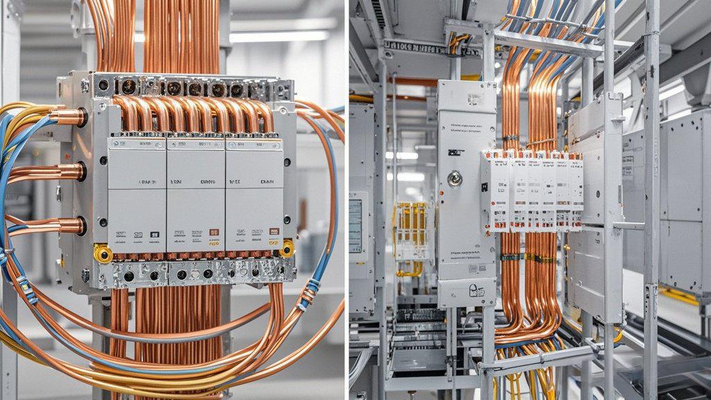
The two primary types of busbar trunking are sandwich-type (compact design with conductors sandwiched between insulation layers) and feeder-type (larger capacity design with spaced conductors for high-current applications). Both provide efficient power distribution with different current capacities and installation requirements.
Choosing between sandwich and feeder trunking depends heavily on your specific application needs. In my experience installing systems across various industrial sites, I've noticed sandwich-type trunking works best in space-constrained environments where moderate power requirements exist. The compact design makes it perfect for office buildings and retail spaces where aesthetics matter.
Feeder-type trunking, on the other hand, excels in high-power industrial applications. Last year, we installed a feeder system in a manufacturing plant that needed to distribute 3000A throughout the facility. The spaced conductor design allowed for better heat dissipation, crucial for handling such high current loads continuously.
Key Differences Between Trunking Types
| Feature | Sandwich-Type | Feeder-Type |
|---|---|---|
| Current Capacity1 | Typically up to 1000A | Can exceed 5000A |
| Space Requirements | Compact, space-saving | Larger footprint |
| Heat Dissipation2 | Good for moderate loads | Superior for high currents |
| Cost3 | Generally lower initial cost | Higher investment but better for heavy loads |
| Typical Applications | Commercial buildings, data centers | Heavy industry, large manufacturing |
When evaluating your needs, consider not just current requirements but future expansion. I've seen too many clients regret choosing systems that couldn't accommodate growth, resulting in expensive retrofits just a few years later.
What Is Main and Auxiliary Bus Bar Arrangement?
Power interruptions disrupt operations and lead to significant financial losses. Scheduled maintenance often requires complete shutdowns. Facilities need solutions that allow for repairs without total power loss.
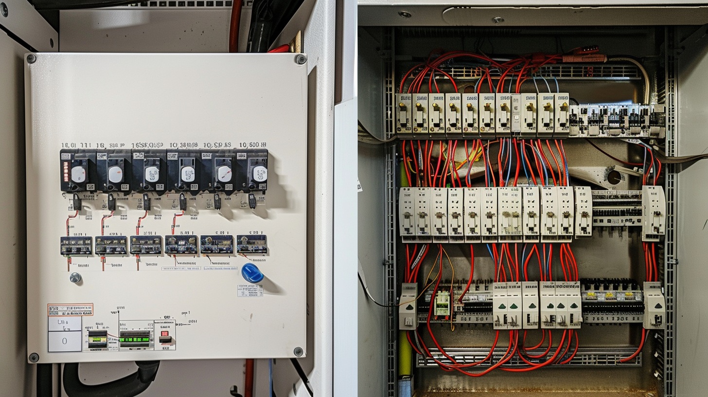
A main and auxiliary busbar arrangement consists of a primary busbar that handles normal operations and a secondary auxiliary busbar that provides backup during maintenance or emergencies. This arrangement allows for continued operation during maintenance by transferring loads to the auxiliary bus.

I've implemented main-auxiliary arrangements in several mid-sized manufacturing facilities, and the operational flexibility they provide is remarkable. One particular project stands out in my mind. A food processing plant couldn't afford even brief outages without spoiling product batches worth thousands of dollars. The main-auxiliary setup we installed allowed them to perform critical maintenance during production hours without interrupting power to sensitive equipment.
The beauty of this arrangement lies in its selective transfer capability. Individual feeders can be moved between buses as needed, rather than switching entire systems. This feature provides a sweet spot between cost and reliability that many businesses find attractive.
Implementation Considerations
The main-auxiliary system requires careful planning of the transfer mechanism. In high-reliability scenarios, I typically recommend automatic transfer switches4 that can shift the load in milliseconds. For less critical applications, manual transfer5 might be sufficient. Here's a breakdown of the components needed:
- Main busbar system with full capacity rating
- Auxiliary busbar with capacity matched to critical loads
- Bus coupler or tie breakers
- Transfer switches (manual or automatic)
- Control and monitoring systems
One important note from my field experience: the auxiliary bus doesn't necessarily need the same capacity as the main bus. By carefully analyzing which loads are truly critical, you can often size the auxiliary system smaller, saving considerable cost without compromising essential operations.
What Is the Difference Between a Single Busbar and a Double Busbar?
System failures create costly downtime. Maintenance requires shutdowns. Engineers must balance reliability needs against budget constraints when selecting power distribution schemes.
A single busbar system has one set of busbars connecting all circuits, making it simpler and less expensive but vulnerable to complete outages. Double busbar systems feature two parallel sets of busbars with interconnection capabilities, providing redundancy and allowing maintenance without interruption.

The difference between these arrangements became crystal clear to me during a project for two neighboring facilities. The first chose a single busbar system to save on initial costs. When a busbar failure occurred due to an unexpected fault, their entire operation shut down for three days, costing them nearly $200,000 in lost production.
Their neighbor had invested in a double busbar system. When they experienced a similar fault the following year, they simply transferred operations to the second bus and repaired the damaged section without any production loss. The additional $75,000 investment in the double system paid for itself many times over in that single incident.
Comparative Analysis of Busbar Systems
The decision between single and double arrangements should factor in several considerations:
| Factor | Single Busbar | Double Busbar |
|---|---|---|
| Initial Cost | Lower (30-50% less) | Higher due to duplicate equipment |
| Reliability | Good but vulnerable to single-point failures6 | Excellent with built-in redundancy |
| Maintenance Flexibility | Requires complete shutdown | Can maintain one bus while the other operates |
| Space Requirements | Compact | Requires approximately double the space |
| Complexity | Simple operation and control | More complex switching and protection schemes |
| Typical Applications | Non-critical operations, budget-constrained projects | Critical infrastructure, data centers, hospitals |
In my experience, the total cost of ownership7 often favors double busbar systems8 for operations where downtime costs exceed $10,000 per hour. The premium paid upfront is typically recovered through avoided outages within the first few years of operation.
What Is the Bus Bar Scheme?
Electrical systems face competing demands for reliability, maintainability, and cost-effectiveness. Engineers struggle to select configurations that balance these needs. Different applications require tailored solutions.
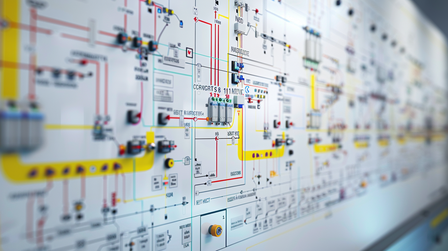
A busbar scheme is the overall arrangement pattern of busbars in a switchgear or distribution system. Common schemes include single busbar, double busbar, main-transfer, ring bus, and breaker-and-a-half configurations, each designed for different reliability and operational requirements.

I recently consulted on a major hospital expansion where selecting the right busbar scheme was crucial. With life-critical equipment depending on power continuity, reliability wasn't optional. We implemented a double busbar scheme with automatic transfer capabilities that could handle their critical loads even during fault conditions or maintenance.
The selected scheme needed to accommodate both present needs and future expansion. We designed the system with section breaks that allowed the hospital to add new wings without disrupting existing services. Five years later, when they added a new imaging center, the foresight in busbar scheme selection made the expansion significantly smoother and less costly.
Beyond the Basics: Specialized Busbar Schemes
Beyond the common arrangements, several specialized schemes serve particular needs:
Ring Bus Scheme9
This arrangement connects busbars in a closed loop, offering excellent reliability since any section can be isolated without affecting other parts. I've found it particularly effective for industrial complexes with distributed loads across large areas.
Breaker-and-a-Half Scheme10
Each circuit connects to both main buses through three circuit breakers shared between two adjacent circuits (hence "one-and-a-half" breakers per circuit). This premium arrangement provides exceptional reliability but at higher cost and complexity.
One-and-One-Half Breaker Scheme11
| Feature | Benefits | Applications |
|---|---|---|
| Redundant Breakers | Maintains service during breaker maintenance | Critical power facilities |
| Multiple Connection Paths | Prevents single points of failure | Substations with vital feeders |
| Isolation Capability | Allows bus maintenance without service interruption | 24/7 operation facilities |
| Complex Protection | Better fault isolation and clearance | High-reliability operations |
From my experience, the scheme selection should align with both technical requirements and organizational priorities. A data center might justify the expense of a breaker-and-a-half scheme due to the extreme cost of downtime, while a warehouse might be perfectly served by a simple single bus arrangement.
Conclusion
Choosing the right busbar arrangement balances reliability against cost. From single bus systems for budget-conscious applications to redundant double arrangements for critical operations, your selection should reflect your organization's risk tolerance and operational priorities.
-
Understanding current capacity is crucial for selecting the right trunking type for your needs, especially for future expansion. ↩
-
Heat dissipation is vital for system efficiency; explore how each type manages heat to ensure optimal performance. ↩
-
Cost is a key factor in decision-making; learn about the long-term investment implications of each trunking type. ↩
-
Explore this link to understand how automatic transfer switches enhance reliability and efficiency in critical applications. ↩
-
This resource will help you determine the scenarios where manual transfer is adequate, ensuring cost-effectiveness without sacrificing safety. ↩
-
Learn about single-point failures to understand the risks associated with single busbar systems and improve your system design. ↩
-
Understanding total cost of ownership can help you make informed decisions about busbar systems and their long-term value. ↩
-
Explore the benefits of double busbar systems, especially in critical operations where reliability is paramount. ↩
-
Explore the benefits of the Ring Bus Scheme for enhanced reliability in industrial applications. ↩
-
Learn how the Breaker-and-a-Half Scheme can provide exceptional reliability for critical power facilities. ↩
-
Discover the advantages of the One-and-One-Half Breaker Scheme for high-reliability operations. ↩


