Confused about "bus" versus "busbar" in electrical systems? This common mix-up can cause problems in project planning. Let's clear up the confusion for good.
A "bus" is an electrical connection point or node in a system diagram. A "busbar" is the actual physical conductor, usually a metal strip, that connects different circuits at that node. Think concept versus physical part.
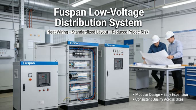
Understanding this difference is more than just words. It affects how we design, build, and talk about electrical systems. As someone supplying components like fuse disconnectors and busbar systems, I see this distinction matter every day. Getting it right helps ensure systems are safe, reliable, and efficient. Let's explore these terms further.
What is the difference between bus and busbar, really?
Still finding the terms bus and busbar slightly confusing? Using the wrong term can lead to mistakes in specifying parts or understanding diagrams. Let’s look closer at what sets them apart.
The key difference is simple: a bus is a concept – a point where circuits meet. A busbar is the physical object – the metal bar or strip that makes the connection happen.
Let's dive deeper into this. The distinction is very important when moving from electrical theory and design to actual installation and procurement.
Conceptual vs. Physical
Think about an electrical schematic diagram1. You see lines representing wires and symbols representing components. A 'bus' on this diagram is often shown as a thick line or a point where multiple circuit lines connect. It represents a location that shares the same electrical potential (voltage). It doesn't specify how that connection is made physically.
A 'busbar2,' on the other hand, is the tangible hardware. It's typically a rectangular bar made of copper or aluminum. You can touch it (carefully!), install it, and bolt connections to it. It's the physical solution chosen to implement the conceptual 'bus'.
Why Does it Matter in Practice?
Understanding this helps in several ways:
| Aspect | Bus (Concept) | Busbar (Physical) |
|---|---|---|
| Stage | Design, Analysis, Planning | Manufacturing, Installation, Maintenance |
| Focus | Electrical connectivity, Voltage level, Node | Material, Size, Shape, Current capacity, Mounting |
| Representation | Symbol on a diagram | Actual component in a panel or switchgear |
| Example | "Connect feeders to the main 400V bus." | "Install a 100x10mm copper busbar for the main panel." |
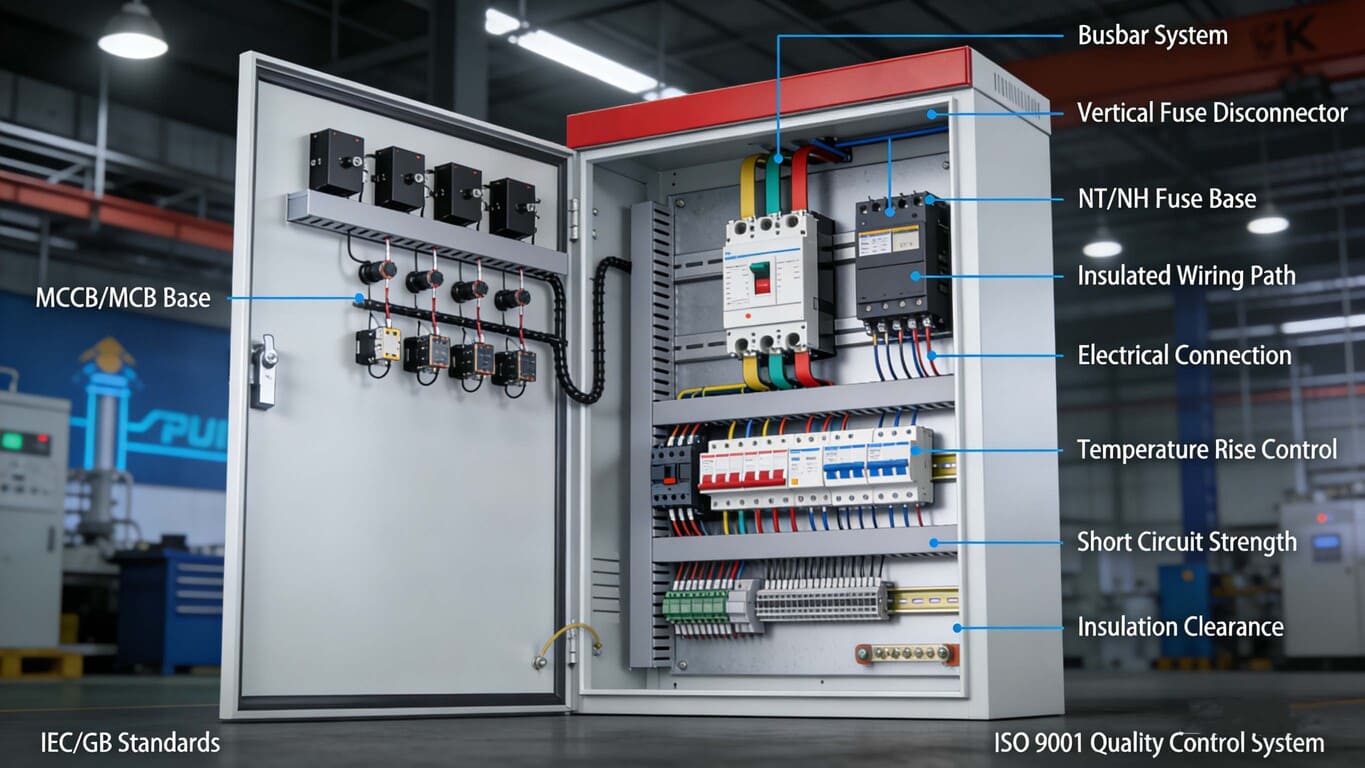
When my team discusses projects with clients like you, Mr. Abdu, being clear about whether we're talking about the connection point (bus) or the conductor (busbar) prevents errors. It ensures the right components, like our NT fuse bases or busbar distribution blocks, are specified for the actual physical requirements of the system design. This clarity is vital for meeting IEC standards3 and ensuring project timelines.
What is a bus in grid?
Heard engineers talk about a 'bus' in the power grid context? Not understanding its role can make grid operations and planning seem confusing. Let's define what a 'bus' means here.
In a power grid, a bus represents a node or junction point in the network. It's where transmission lines, generators, and loads connect. It signifies a point of common voltage.

Let's explore the function of these buses within the larger electrical grid infrastructure. They are fundamental building blocks for managing power flow.
The Role of Buses in Grid Operations
Think of the power grid4 like a complex road network. A 'bus' acts like a major intersection or interchange. It’s a point where electrical power can change paths. Different elements connect here:
- Generators: Power plants feed electricity into the grid at generator buses.
- Loads: Factories, cities, and homes draw power from the grid at load buses.
- Transmission/Distribution Lines: Power is transported between buses via these lines.
Importance in Grid Analysis
Engineers use the concept of buses extensively in power system studies. These studies help ensure the grid operates reliably and efficiently. Key aspects include:
- Voltage Levels5: Each bus is associated with a specific voltage level (e.g., 400kV, 132kV, 11kV). Maintaining voltage within limits at each bus is critical.
- Power Flow: Analyzing how power moves between buses helps identify potential overloads or losses.
- Fault Analysis6: Simulating short circuits at different buses helps design protective systems (like those using our fuse switch disconnectors).
- Stability: Assessing how the grid responds to disturbances often focuses on the behavior of key buses.
There are even different types of buses used in these analyses: - Slack Bus (or Swing Bus): Balances power generation and load in the system model.
- Generator Bus (or PV Bus): Voltage magnitude is controlled here.
- Load Bus (or PQ Bus): Real and reactive power consumption is specified here.
For EPC contractors involved in grid projects, understanding the bus concept is essential for interpreting single-line diagrams and appreciating the requirements for connected equipment. Ensuring components meet the specified voltage and fault levels at their connecting bus is crucial for grid integrity.What is the difference between a bus duct and a busbar?
You know what a busbar is, but now you hear "bus duct"? This can add another layer of confusion when choosing power distribution methods. Let's clarify what a bus duct is.
A bus duct (or busway) is an enclosure containing busbars. It's a system that protects the busbars inside, providing safety and a structured way to distribute power, unlike bare busbars.

Why choose a bus duct over simply using exposed busbars? The reasons often relate to safety, environment, and ease of installation, especially in industrial or commercial settings.Protection and Safety
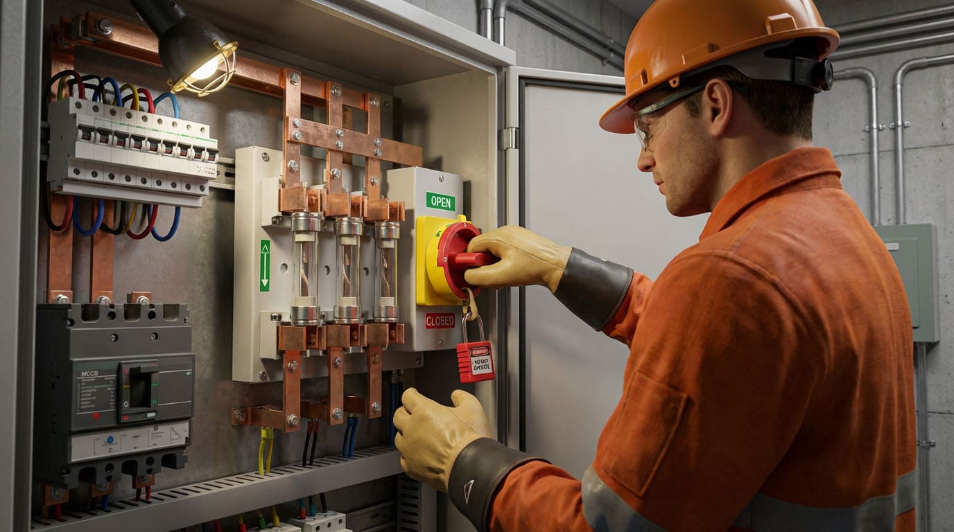
Exposed busbars, while effective conductors, present safety risks. They are open to accidental contact and environmental factors like dust, moisture, or corrosive elements. A bus duct encloses the busbars, usually in a metal housing. This provides significant benefits:
- Safety: Protects personnel from direct contact with live conductors.
- Environmental Protection7: Shields busbars from physical damage, dust, and moisture ingress (IP rating).
- Reduced Fault Risk8: Minimizes the chance of phase-to-phase or phase-to-ground faults caused by external objects or contamination.
Installation and Scalability
Bus ducts often come in prefabricated sections. This modularity can simplify installation compared to custom-fitting bare busbars on-site.
- Faster Installation9: Standardized sections can be quicker to assemble.
- Flexibility: Tap-off points can be easily added along the duct run to supply power to equipment.
- Space Efficiency: Can sometimes offer a more compact solution than cable trays, especially for high currents.
Here's a quick comparison:
| Feature | Bare Busbar | Bus Duct / Busway |
|---|---|---|
| Enclosure | None | Metal housing (steel, aluminum) |
| Protection | Low (relies on panel enclosure) | High (self-contained protection) |
| Safety | Requires careful guarding | Enhanced safety due to enclosure |
| Environment | Susceptible to dust, moisture, damage | Protected from environment (IP rated) |
| Installation | Custom fitting, requires skilled labor | Modular sections, potentially faster assembly |
| Application | Switchgear panels, compact distribution points | Power distribution runs (feeders, risers) |
As a manufacturer, Fuspan sees growing interest in enclosed systems like bus ducts, especially in industrial settings where safety and reliability are paramount. While we focus on components like fuse holders and distribution blocks that connect to busbars (whether bare or enclosed), we understand the system context. Choosing between bare busbars and bus ducts depends heavily on the specific project needs, environment, and safety regulations – factors crucial for procurement decisions.
What is the bus bar in a grid station?
Thinking specifically about substations or grid stations? What exactly is the role of the busbar in this critical infrastructure? Let's pinpoint its function within a grid station.
In a grid station (substation), the busbar is the main electrical conductor acting as a central connection hub. It collects power from incoming lines and distributes it to outgoing feeders and transformers.

Busbars are truly the backbone of any substation, ensuring power flows correctly and reliably between different parts of the electrical network. Let's look closer at their specific role.
The Central Hub of the Substation
Imagine a substation as a major sorting center for electricity. Busbars are the main conveyor belts or platforms:
- Connection Point: All major circuits within the substation – incoming transmission lines, outgoing distribution feeders, power transformers, circuit breakers, isolators – connect to the busbars10.
- Maintaining Voltage: They provide a common voltage reference point for all connected circuits.
- Distributing Current: They carry large amounts of electrical current, requiring them to be substantial conductors, typically made of high-conductivity copper or aluminum.
Physical Characteristics and Configurations
In substations, busbars are often large, rigid conductors, either rectangular bars or sometimes tubes, especially for very high voltages/currents. They are mounted on insulators to prevent electricity from leaking to the support structures. You'll see them prominently in both indoor switchgear rooms and outdoor switchyards.
Substations use different busbar arrangements for varying levels of reliability and flexibility: - Single Busbar: Simplest, lowest cost, but maintenance requires shutting down the whole section.
- Double Busbar: Allows circuits to be switched between two buses, enabling maintenance without full shutdown. More flexible and reliable, but more complex and costly.
- Ring Bus: Circuits are connected in a loop, offering good reliability as any one section can be isolated.
Importance for Reliability and Protection
The integrity of the busbar system is critical for the substation's operation. Failures here can cause widespread outages. Protective relays and circuit breakers are connected to monitor the busbars and quickly isolate faults. Components like Fuspan's vertical fuse switch disconnectors play a role in protecting circuits branching off these main busbars. For procurement managers like Mr. Abdu, ensuring the busbars and associated connection components meet stringent IEC standards11 and can handle the specified fault currents is absolutely essential for large-scale energy projects. The reliability demanded by your projects starts right here, at the substation busbar.
Conclusion
In short, a bus is a connection concept in diagrams, while a busbar is the physical conductor. Understanding this helps design and build safer, more reliable electrical systems for any project.
-
This resource will help you master reading electrical schematics, crucial for effective communication in engineering projects. ↩
-
Explore this link to understand the significance and applications of busbars in electrical systems, enhancing your project knowledge. ↩
-
Learn about IEC standards to ensure compliance and quality in your electrical projects, which is essential for success. ↩
-
Understanding the power grid's role is essential for grasping how electricity is distributed and managed across regions. ↩
-
Exploring voltage levels helps you understand their critical role in maintaining grid stability and efficiency. ↩
-
Learning about fault analysis provides insights into how power systems prevent failures and ensure safety. ↩
-
Explore how environmental protection in bus duct systems enhances safety and reliability, crucial for industrial applications. ↩
-
Discover how reduced fault risk in bus duct systems can prevent costly downtime and enhance operational safety. ↩
-
Learn about the advantages of faster installation in bus duct systems, making them a preferred choice for efficient power distribution. ↩
-
Understanding busbars is crucial for grasping how substations distribute electricity efficiently and safely. ↩
-
Learning about IEC standards is vital for ensuring compliance and safety in large-scale energy projects. ↩